Discovery 2. Manual - part 453


  Index      Land Rover     Land Rover Discovery 2 - service manual 1999 year


Search            


Content   ..  451  452  453  454   ..


Discovery 2. Manual - part 453


EMISSION CONTROL - V8

DESCRIPTION AND OPERATION 17-2-11

Changes in the oxygen content has subsequent effects on the levels of exhaust emissions experienced. The levels 
of hydrocarbons and carbon monoxide produced around the stoichiometric ideal control range are minimised, but 
peak emission of oxides of nitrogen are experienced around the same range.

Fuel metering
For a satisfactory combustion process, precise fuel injection quantity, timing and dispersion must be ensured. If the 
air:fuel mixture in the combustion chamber is not thoroughly atomized and dispersed during the combustion stroke, 
some of the fuel may remain unburnt which will lead to high HC emissions.

Ignition timing
The ignition timing can be changed to minimise exhaust emissions and fuel consumption in response to changes due 
to the excess air factor. As the excess air factor increases, the optimum ignition angle is advanced to compensate for 
delays in flame propagation.

Exhaust emission control components
The exhaust emission control components are described below:
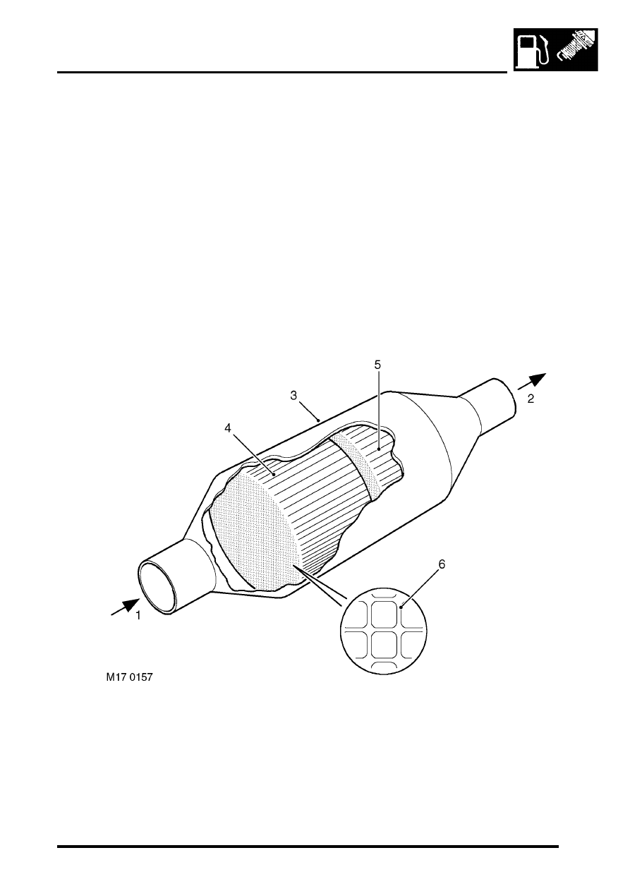
Catalytic converter

Exhaust gas from manifold
Cleaned exhaust gas to tail pipe
Catalytic converter outer case

1st ceramic brick
2nd ceramic brick
Honeycomb structure

The catalytic converters are located in each of the front pipes from the exhaust manifolds.

EMISSION CONTROL - V8

17-2-12 DESCRIPTION AND OPERATION

The catalytic converter's housings are fabricated from stainless steel and are fully welded at all joints. Each catalytic 
converter contains two elements comprising of an extruded ceramic substrate which is formed into a honeycomb of 
small cells with a density of 62 cells / cm

2

. The ceramic element is coated with a special surface treatment called 

'washcoat' which increases the surface area of the catalyst element by approximately 7000 times. A coating is applied 
to the washcoat which contains the precious elements Platinum, Palladium and Rhodium in the following relative 
concentrations: 1 Pt : 21.6 PD : 1 Rh

Catalytic converters for NAS low emission vehicles (LEVs) from 2000MY have active constituents of 
palladium and rhodium only. The active constituents are 14PD: 1Rh and the palladium coating is used to 
oxidise the carbon monoxide and hydrocarbons in the exhaust gas.

The metallic coating of platinum and palladium oxidize the carbon monoxide and hydrocarbons and convert them into 
water (H

2

O) and carbon dioxide (CO

2

). The coating of rhodium removes the oxygen from nitrogen oxide (NO

x

) and 

converts it into nitrogen (N

2

).

CAUTION: Catalytic converters contain ceramic material, which is very fragile. Avoid heavy impacts on the 
converter casing.

Downstream of the catalytic converters, the exhaust front pipes merge into a single pipe terminating at a flange joint 
which connects to the exhaust intermediate pipe. 

WARNING: To prevent personal injury from a hot exhaust system, do not attempt to disconnect any 
components until the exhaust system has cooled down.

CAUTION: Serious damage to the catalytic converter will occur if leaded fuel is used. The fuel tank filler neck 
is designed to accommodate only unleaded fuel pump nozzles.

CAUTION: Serious damage to the engine may occur if a lower octane number fuel than recommended is used. 
Serious damage to the catalytic converter will occur if leaded fuel is used.

Heated oxygen sensor

Connection cable
Disc spring
Ceramic support tube
Protective sleeve
Clamp connection for heating element
Heating element
Contact element

Sensor housing
Active sensor ceramic

10 Protective tube
11 Post-catalytic converter sensor (NAS spec. 

only)

12 Pre-catalytic converter sensor

EMISSION CONTROL - V8

DESCRIPTION AND OPERATION 17-2-13

The heated oxygen sensor is an integral part of the exhaust emission control system and is used in conjunction with 
the catalytic converters and the engine management control unit to ensure that the air:fuel mixture ratio stays around 
the stoichiometric point of 

λ

 = 1, where the catalytic converters are most effective. Combinations of four (NAS only) 

or two heated lambda sensors are used in the exhaust system dependent on market legislation.

The heated oxygen sensor is screwed into threaded mountings welded into the top of the front exhaust pipes at 
suitable locations. They are used to detect the level of residual oxygen in the exhaust gas to provide an instantaneous 
indication of whether combustion is complete. By positioning sensors in the stream of exhaust gases from each 
separate bank of the exhaust manifold, the engine management system is better able to control the fuelling 
requirements on each bank independently of the other, so allowing much closer control of the air:fuel ratio and 
optimising catalytic converter efficiency.

Two pre-catalytic converter heated oxygen sensors are mounted in the front pipes for monitoring the oxygen content 
of the exhaust gas. NAS models also have two additional post-catalytic converter heated oxygen sensors in the 
exhaust front pipe.

CAUTION: HO2 sensors are easily damaged by dropping, over torquing, excessive heat or contamination. 
Care must be taken not to damage the sensor housing or tip.

The oxygen sensors consist of a ceramic body (Galvanic cell) which is a practically pure oxygen-ion conductor made 
from a mixed oxide of zirconium and yttrium. The ceramic is then coated with gas-permeable platinum, which when 
heated to a sufficiently high temperature (

 350

°

 C) generates a voltage which is proportional to the oxygen content 

in the exhaust gas stream.

The heated oxygen sensor is protected by an outer tube with a restricted flow opening to prevent the sensor's 
ceramics from being cooled by low temperature exhaust gases at start up. The post-catalytic sensors have improved 
signal quality, but a slower response rate.

The pre-catalytic and post-catalytic converter sensors are not interchangeable, and although it is possible to mount 
them in transposed positions, their harness connections are of different gender and colour. It is important not to 
confuse the sensor signal pins; the signal pins are gold plated, whilst the heater supply pins are tinned, 
mixing them up will cause contamination and adversely affect system performance.

Each of the heated oxygen sensors have a four pin connector with the following wiring details:

l

Sensor signal ground (grey wire – connects to engine management ECM)

l

Sensor signal (black wire – connects to engine management ECM)

l

Heater drive (white wire – connects to engine management ECM)

l

Heater supply (white wire – connects to fuse 2, underbonnet fuse box)

The ECM connector pins for exhaust emission control are listed in the following table:

ECM Connector 2 (C635) pin-out details for exhaust emission control system

Pin Number

Function

Signal Type

Control

2-01

Post-cat sensor heater (RH) - NAS only

Output, Drive

PWM, 12 - 0V

2-07

Post-cat sensor heater (LH) - NAS only

Output, Drive

PWM, 12 - 0V

2-08

Post-cat sensor (RH) - NAS only

Ground, Signal

0V

2-09

Pre-cat sensor (LH)

Ground, Signal

0V

2-10

Pre-cat sensor (RH)

Ground, Signal

0V

2-11

Post-cat sensor (LH) - NAS only

Ground, Signal

0V

2-13

Pre-cat sensor heater (RH)

Output, Drive

PWM, 12 - 0V

2-14

Post-cat sensor (RH) - NAS only

Input, Signal

Analogue, 0 - 1V

2-15

Pre-cat sensor (LH)

Input, Signal

Analogue, 0 - 1V

2-16

Pre-cat sensor (RH)

Input, Signal

Analogue, 0 - 1V

2-17

Post-cat sensor (LH) - NAS only

Input, Signal

Analogue, 0 - 1V

2-19

Pre-cat sensor heater (LH)

Output, Drive

PWM, 12 - 0V

EMISSION CONTROL - V8

17-2-14 DESCRIPTION AND OPERATION

The heated oxygen sensors should be treated with extreme care, since the ceramic material within them can be easily 
cracked if dropped, banged or over-torqued; the sensors should be torqued to the recommended values indicated in 
the repair procedures. Apply anti-seize compound to the sensor's threads when refitting.

WARNING: Some types of anti-seize compound used in service are a health hazard. Avoid skin contact.

WARNING: To prevent personal injury from a hot exhaust system, do not attempt to disconnect any 
components until the exhaust system has cooled down.

CAUTION: Do not allow anti-seize compound to come into contact with tip of sensor or enter exhaust system.

NOTE: A new HO2 sensor is supplied pre-treated with anti-seize compound.


Content   ..  451  452  453  454   ..