Discovery 2. Manual - part 169


  Index      Land Rover     Land Rover Discovery 2 - service manual 1999 year


Search            


Content   ..  167  168  169  170   ..


Discovery 2. Manual - part 169


STEERING

DESCRIPTION AND OPERATION

57-11

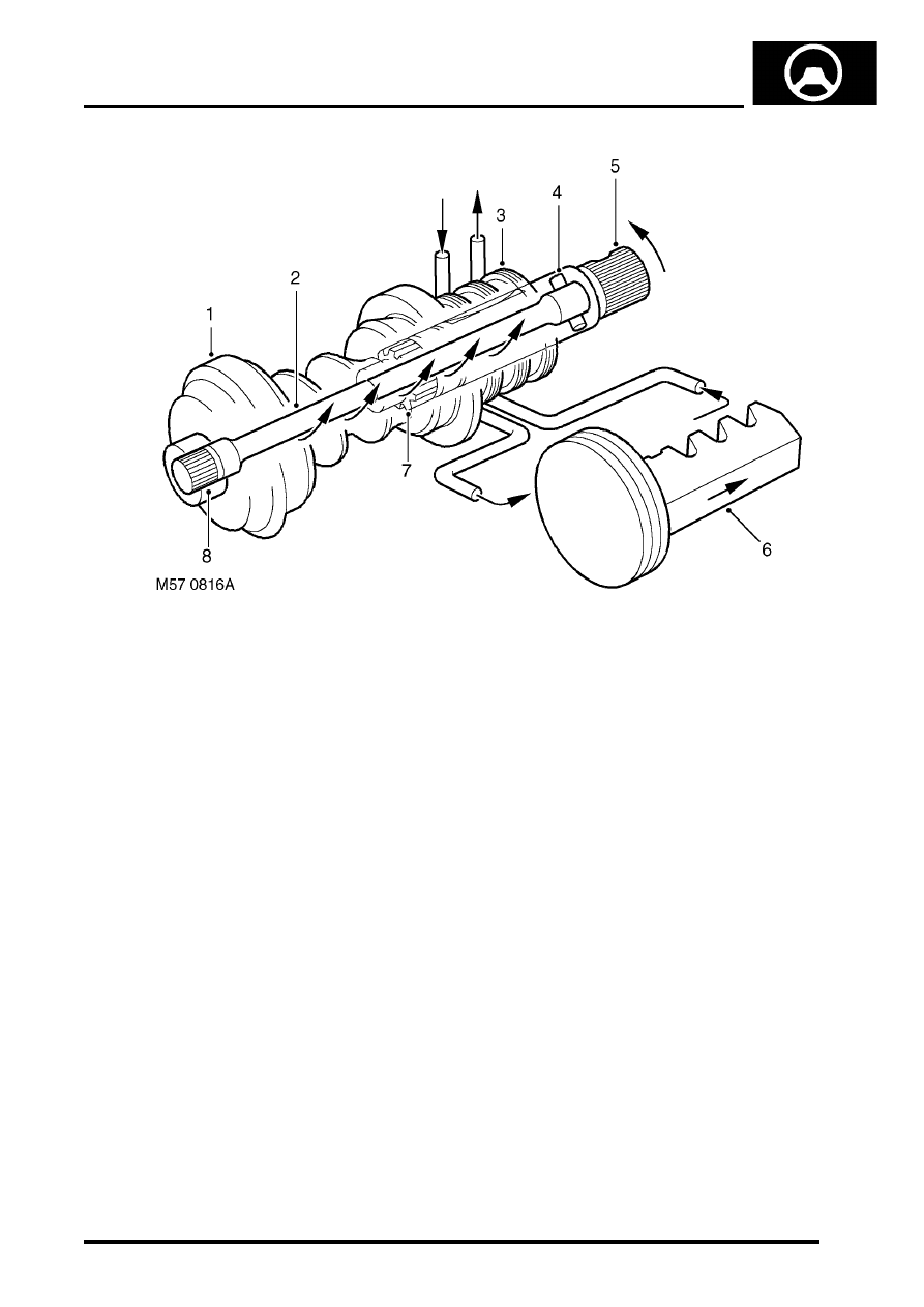
Rotary control valve in demand mode

Worm gear
Torsion bar
Valve sleeve
Pin

Input shaft and valve rotor
Piston/rack
Coarse spline
Spline (torque shaft to worm gear)

When the steering wheel and input shaft is turned steering resistance transmitted to the worm causes the torsion bar 
to be wound up and the valve ports in the valve rotor and valve sleeve to be aligned for a right or left turn. The 
alignment of the valve ports directs fluid pressure  'A' from the PAS pump to one side of the piston/rack . The other 
side of the piston/rack is now connected to return 'B' (due the valves port alignment) and displaced fluid returns to the 
reservoir. The pressure difference in the cylinder on each side of the piston gives the power assistance to move the 
rack and so turn the steering.

The greater the resistance of the road wheels to the steering rotary movement, the greater torque acting on the torsion 
bar and input shaft causing greater changes of alignment of the ports in the valve. As the change of alignment 
becomes greater, the fluid pressure passing to the applicable side of the piston/rack increases.

Only when the steering wheel stops turning and the torsion bar has unwound, will the valve rotor return to the neutral 
position. In the neutral position the fluid circulates through the ports in the valve rotor and valve sleeve and back to 
the reservoir where it is cooled.

STEERING

57-12

DESCRIPTION AND OPERATION

PAS pump - V8

Bolt 2 off
Nut
Stud
Auxiliary housing
PAS pump

Outlet
Inlet
Bolt 3 off
Drive pulley

The PAS pump is located on the auxiliary housing and is attached by two bolts, the bolts go through flanged bushes 
in the auxiliary housing. A stud passes through the PAS pump and through a flanged bush in the auxiliary housing, 
the auxiliary housing and PAS pump are secured by a nut. As the two bolts and nut are tightened the bushes move 
slightly and the flange of each bush clamps the PAS pump. A drive pulley is attached to the pump drive shaft with 
three bolts, and is belt driven at a ratio of 1.4 crankshaft revolutions to 1 of the drive pulley. Fluid is drawn into the 
PAS pump inlet from the reservoir through a flexible hose at low (suction) pressure. Fluid at high pressure from the 
PAS pump outlet is supplied to the rotary control valve on the steering box.

The PAS pump is a roller vane type and has an internal pressure regulator and flow control valve. The roller vanes 
can move in slots in the pumps rotor and are moved outwards by centrifugal force as the pump rotates. The pump 
rotor rotates in the pump housing, the internal shape of the housing forms a 'cam' shape. Due to the 'cam' shape the 
volume of the housing decreases between the inlet and outlet ports.

As the pump rotor rotates towards the pump inlet the volume between the roller vanes and the pump housing 
increases, this action causes a depression in the chamber between the pump roller vanes and the housing. As the 
rotation continues the chamber is opened to the pump inlet, and the depression in the chamber causes fluid to be 
drawn in. The roller vanes continue past the inlet port, closing off the inlet port and trapping the fluid in the chamber 
between the rollers and the pump housing.

STEERING

DESCRIPTION AND OPERATION

57-13

The internal 'cam' shape of the pump housing causes the rollers to move closer together as the pump rotor rotates 
towards the outlet port. The reduced volume of the chamber between the roller vanes causes the fluid to become 
pressurised. When the chamber is opened to the outlet port of the pump the fluid escapes at high pressure. The roller 
vanes continue turning and go past the outlet port, closing off the chamber between the two roller vanes.

As rotation continues the inlet sequence begins again. The inlet and pressurisation/outlet sequences continue as the 
pump rotates, and is repeated between each two roller vanes. The pump is a positive displacement type and the 
potential pump output increases with engine (drive pulley) speed. The pressure relief and flow control valve regulates 
flow/pressure by diverting fluid back to the pump inlet through internal recirculation passages in the pump body.

STEERING

57-14

DESCRIPTION AND OPERATION

PAS pump - diesel

Drive pulley
Mounting bracket
Bolt 2 off
Bolt
PAS pump
Coupling

Auxiliary housing
Outlet
Inlet adaptor pipe and seal

10 Bolt 2 off
11 Bolt 2 off
12 Bolt 3 off

The PAS pump is located on the auxiliary housing, two bolts go through the PAS pump, mounting bracket and into 
the auxiliary housing. One bolt also attaches the mounting bracket to the PAS pump, two bolts secure the mounting 
bracket to the auxiliary housing. An inlet adaptor pipe with a seal is secured to the bottom of the pump with two bolts. 
A drive pulley is attached to the pump drive shaft with three bolts, and is belt driven at a ratio of 1.35 crankshaft 
revolutions to 1 of the drive pulley. A coupling on the rear of the PAS pump rotates the water pump impeller located 
in the auxiliary housing. Fluid is supplied to the PAS pump inlet from the reservoir through a flexible hose at low 
(suction) pressure. Fluid at high pressure from the PAS pump outlet is supplied to the rotary control valve on the 
steering box.

The PAS pump is a roller vane type and has an internal pressure regulator and flow control valve. The roller vanes 
can move in slots in the pumps rotor and are moved outwards by centrifugal force as the pump rotates. The pump 
rotor rotates in the pump housing, the internal shape of the housing forms a 'cam' shape. Due to the 'cam' shape the 
volume of the housing decreases between the inlet and outlet ports.


Content   ..  167  168  169  170   ..