Land Rover Discovery. Manual - part 89


  Index      Land Rover     Land Rover Discovery - service 1995-1996 year


Search            


Content   ..  87  88  89  90   ..


Land Rover Discovery. Manual - part 89


V8i

1

DESCRIPTION AND OPERATION

ENGINE COOLING

Description

The V8i engine uses a pressurised cooling system
and cross flow radiator which is supplied from a
separate header tank. The coolant radiator also
incorporates a section at the left hand end for cooling
the transmission oil and a section at the other end for
cooling the engine oil.

The belt driven viscous fan and centrifugal water
pump is located in the engine front cover with ports for
circulation of coolant to both banks of cylinders and
cylinder heads. Coolant returns to the top of the
radiator via ports in the inlet manifold where the
thermostat is mounted horizontally.
Coolant also circulates through the vehicle heating
system and is used to heat air entering the inlet
manifold plenum chamber.

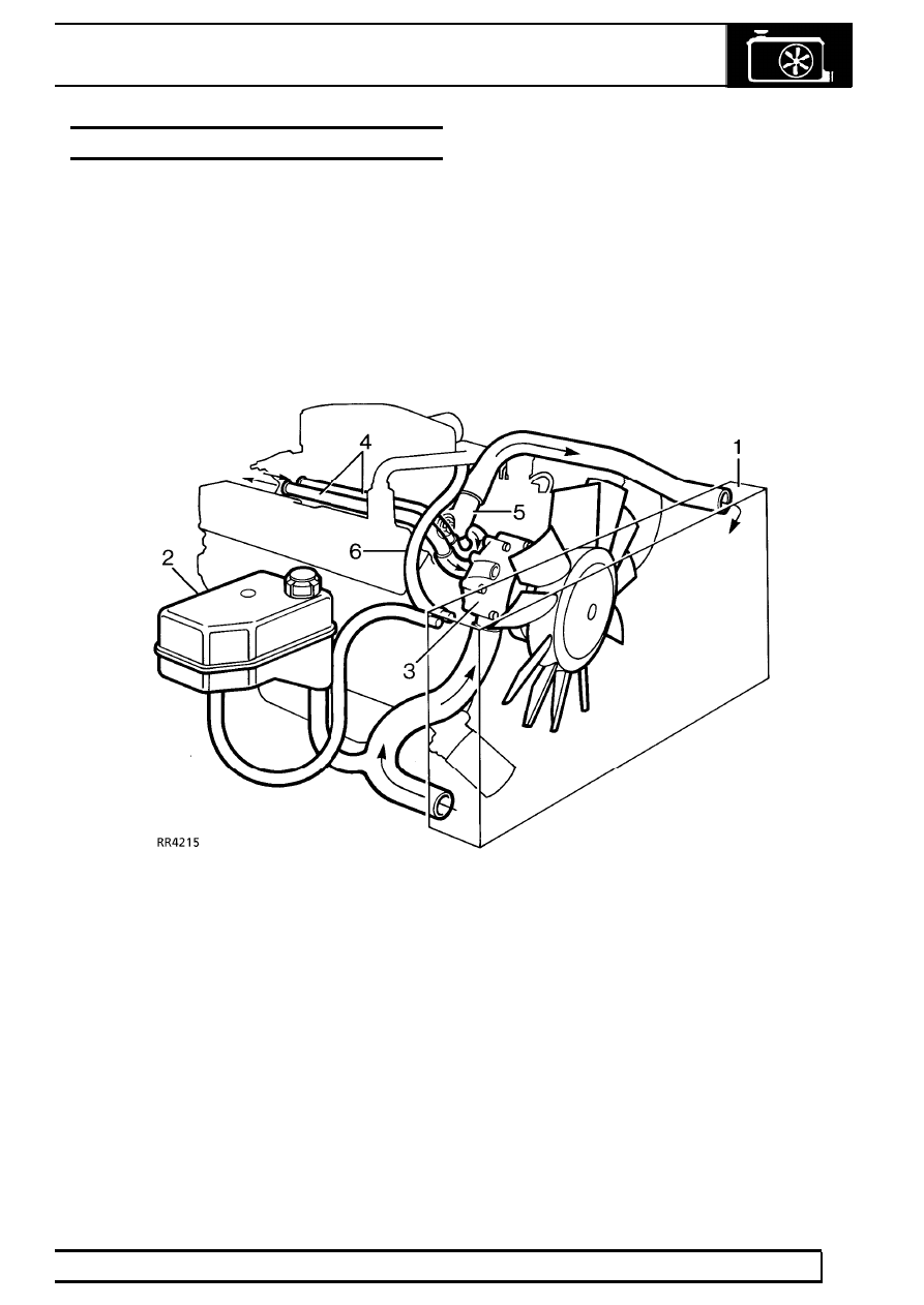
Coolant circulation (engine hot)

1. Cross flow radiator
2. Header tank
3. Viscous fan and water pump
4. Heater pipes
5. Plenum chamber connection
6. Thermostat

26

COOLING SYSTEM

2

DESCRIPTION AND OPERATION

COOLANT CIRCULATION

Operation

When the engine is started from cold the thermostat
prevents any coolant circulation through the radiator
by closing off the top hose. During the engine warm
up period, the water pump, pumps coolant around the
cylinders to the rear of the cylinder block along the
main galleries in both cylinder banks. At the rear of
the cylinder block the coolant rises through a large
port in each cylinder head/block joint face, and then
flows forward to connect with ports at the front of the
inlet manifold. From the manifold the coolant is carried
by an external pipe to the heater unit and from the
heater through another external pipe to the pump
inlet.

The coolant circulation through the cylinder block and
heads, does not change when normal running
temperature is reached and the thermostat opens. But
with the thermostat open, coolant flows through the
top hose to the radiator where it is cooled and drawn
back into the pump via the bottom hose.

V8i

3

DESCRIPTION AND OPERATION

Plenum chamber heating

Air entering the plenum chamber is heated by a flow
of coolant from the inlet manifold which returns
through a long hose, to the top right corner of the
radiator.

1. Hot water supply
2. Cold return to radiator

VISCOUS FAN

Description

The viscous drive unit for the engine cooling fan,
provides a means of controlling the speed of the fan
relative to the running temperature of the engine. The
viscous unit is a type of fluid coupling, which drives
the fan blades through the medium of a special
’silicone fluid’ injected into the unit during
manufacture.

1. Drive in from water pump spindle
2. Drive out to fan blades
3. Bi-metal

26

COOLING SYSTEM

4

DESCRIPTION AND OPERATION

Operation

The viscous unit consists of two principal components:
An inner member 1 which is secured to water pump
spindle and is driven by the fan belt.
An outer member 2 which has the fan blades
attached, houses the working parts and is driven
through the medium of the viscous fluid.

The inner and outer members have interlocking
annular grooves machined in each, with a small
running clearance 3 to allow the silicone fluid to
circulate through the valve plate 4.
The unit also contains a valve 5 which is controlled by
an external bi-metal thermostat 6.

Starting engine from cold

During the time the engine is at rest the silicone fluid
drains down, half filling chambers A and B. Thus when
the engine is first started sufficient fluid is present in
chamber A to provide a positive drive between the
members, as is evident by the initial noise of the fan.
However within a very short period of time, after
starting the engine, the fan speed and noise will
decline indicating that the fluid is being centrifuged
into chamber B (as seen in RR3757M) causing the
drive to slip.

Viscous unit slipping (Engine at normal running
temperature)

1. Inner member (drive in fast)
2. Outer member (drive out slow)
3. Running clearance
4. Valve plate
5. Valve (closed)
6. Bi-metal
7. Fluid seals
8. Ball race

A. Fluid chamber
B. Fluid chamber

If the engine speed is increased the degree of slip will
also increase to limit the maximum fan speed.


Content   ..  87  88  89  90   ..