Defender 90 / 110 / 130. Manual - part 46
CYLINDER ENGINE
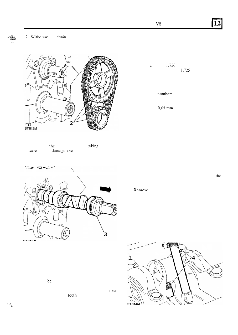
the
wheels complete with timing
6. Measure t h e camshaft journals for overall wear,
ovality and taper. The diameters of the five
journals are as follows commencing from the front
of the shaft.
chain.
3. Withdraw
camshaft whilst
particular
not
to
bearings
in
t h e
cylinder
block.
\
...
,
....
.
.
Examine components
4.
Visually examine all parts
for wear. Check t h e
camshaft bearing journals and cams
for wcar, pits,
scores and overheating. Should any of these
conditions
present the shaft should be renewed.
5. Examine the links and pins of the timing chain
for
wcar and compare its condition with that of
a
chain. Similarly the
of
t h e
chain wheels
should be inspected
a n d
i f
necessary the wheels
should be renewed.
Number 1 journal 1.786 to 1.785 ins
Number journal
to 1.755 ins
Number
3 journal 1.726 to
ins
Number 4 journal 1.696 to 1.695 ins
Number
5 journal 1.666
to 1.665 ins
7.
To check the camshaft for bow, rest the two end
journals i.e.
1
and
5
on ‘V’ blocks and
mount a dial gauge
on the centre journal. Rotate
t h e
shaft and note the reading.
If
the run
out is
more than
(0.002 in)
it
should be
renewed.
REMOVE AND OVERHAUL CONNECTING-RODS
AND
PISTONS
1.
Withdraw the remaining bolts and remove
2. Remove the sump oil strainer.
3.
the connccting-rod caps and retain them
in
sequence for reassembly.
4.
Screw the guide bolts
605351 onto the connecting-
rods.
sump.
continued
103