Defender (1999-2002). Manual - part 80
TRANSFER GEARBOX
1
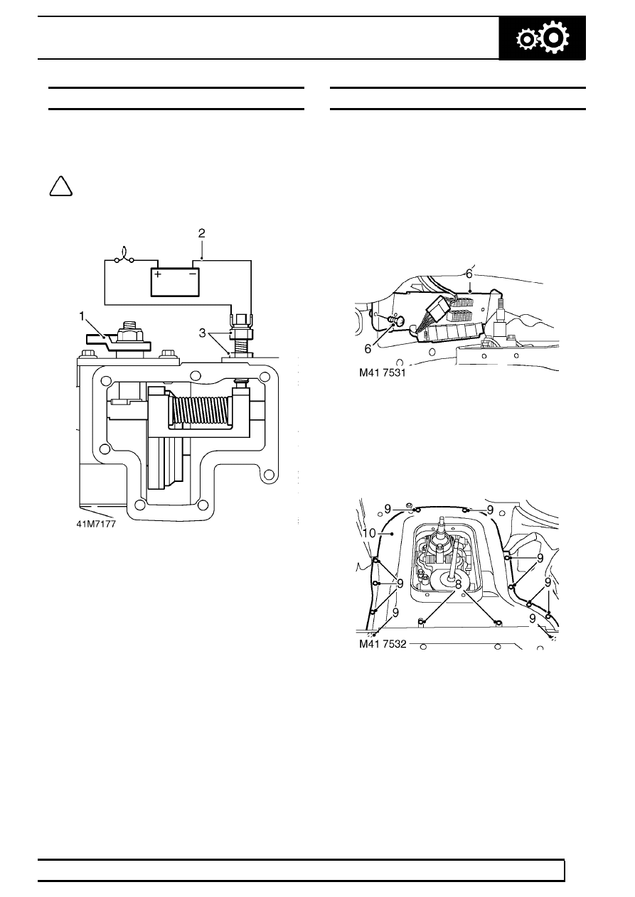
ADJUSTMENT
DIFFERENTIAL LOCK WARNING LAMP SWITCH
Service repair no - 41.20.36
Adjust
NOTE: This procedure is only necessary
for switches fitted with a locknut in place
of the threaded spacer.
1. Move differential lock selector fork to differential
locked position.
2. Connect a 12V test lamp and battery to
differential lock warning lamp switch.
3. Screw switch in until test lamp is illuminated then
screw switch in a further 1/2 turn; tighten locknut.
4. Disengage differential lock, check that test lamp
is extinguished.
5. Remove test lamp.
HIGH/LOW SELECTOR LINKAGE
Service repair no - 41.20.46
Adjust
1. Disconnect battery negative lead.
2. Remove gear lever knobs.
3. Remove gearbox tunnel carpet.
4. Remove gear lever (s) gaiter.
5. Release and remove insulation pad from around
gear levers.
6. Remove 2 screws securing relay/fuse panel and
collect 2 spacers.
7. Release bulkhead carpet from LH side of tunnel
and move aside.
8. Remove 2 bolts securing hand-brake lever to
body and move aside.
9. Remove 13 screws securing tunnel cover.
10. Release and remove tunnel cover.
11. Loosen linkage locknut.