Defender. Manual - part 61


  Index      Land Rover     Land Rover Defender - service manual 2007 year


Search            


Content   ..  59  60  61  62   ..


Defender. Manual - part 61


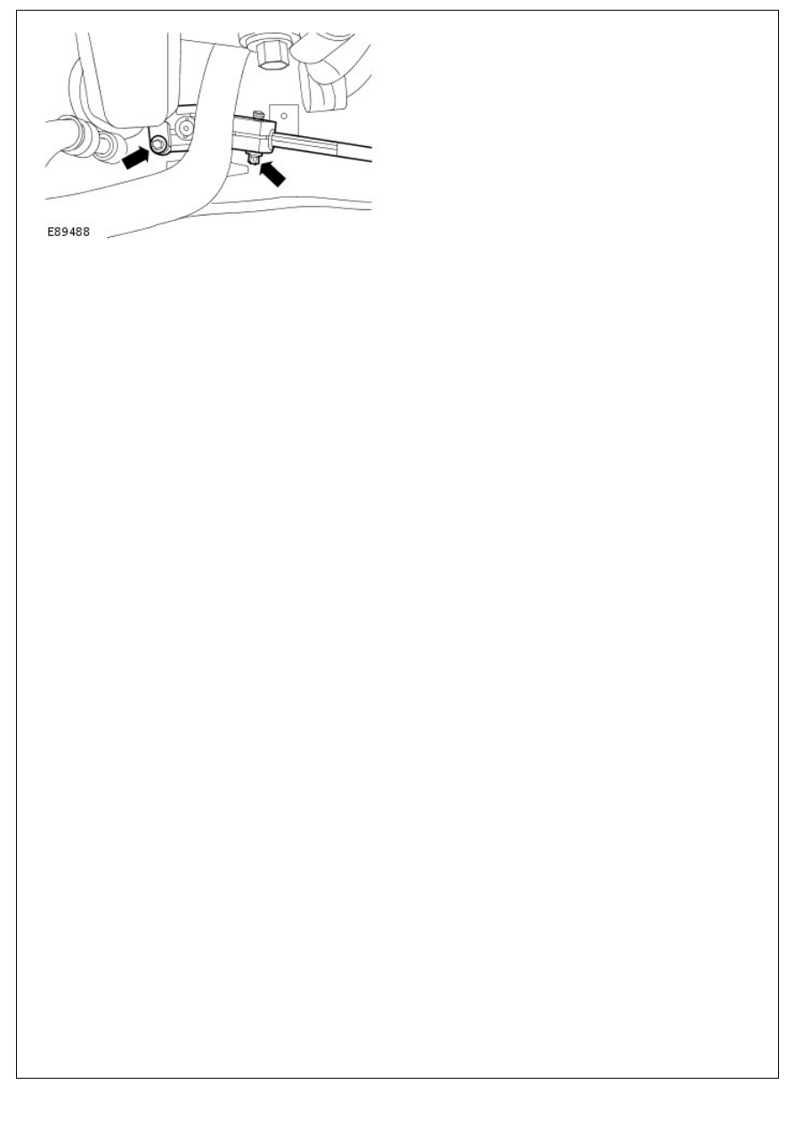
2. Tighten to 30 Nm (22 lb.ft).

Steering Column - Steering Wheel

Removal and Installation

Special Tool(s)

Remover, Steering Wheel

211-295

Removal

• NOTE: Make sure that the wheels and tires are in the straight-ahead position.

1. Remove the steering wheel center pad.

2. Remove the steering wheel nut and locking washer.

3. Mark the relationship between the steering wheel and

steering column.

4. Using the special tool, remove the steering wheel.

4. Using the special tool, remove the steering wheel.

Installation

1. NOTE: Make sure the alignment marks are correctly

aligned.

Install the steering wheel.

Tighten to 43Nm (32 lb.ft).

2. Install the steering wheel center pad.

Steering Column Switches - Steering Column Switches

Description and Operation

OVERVIEW

The steering column switches comprise the steering column multifunction switch and the ignition switch. Both switches

are located on the steering column assembly.

The steering column multifunction switch comprises a case, which houses a turn signal indicator switch assembly and a

windshield wiper switch assembly. The multifunction switch is located behind the steering wheel and is secured at the

top of the steering column assembly and at the bottom of the column lock housing.

LEFT HAND COLUMN SWITCH

Turn Signal Indicator Switch

The turn signal indicator switch assembly is located in the Left Hand (LH) side of the case. The switch is connected to

the main harness via a connector on the back of the switch. The switch controls the following functions:

Left/right turn signal operation

High/low beam operation

Headlamp flash

Horn operation

The turn signal indicators are operated by pushing the switch up for Right Hand (RH) indicators and down for LH

indicators. The switch has a detent position, which locks the switch in the selected position until it is moved to the

central off position. The LH and RH turn signal indicator switch positions are connected on separate wires to the hazard

warning relay, via the hazard warning switch. When a switch position selection is made, a circuit is completed from the

hazard warning relay to ground, via the selected switch position. The hazard warning relay detects the completed circuit

and operates the selected turn signal indicator until the switch is moved to the central off position. The turn signal

indicators can be cancelled either manually by the driver or automatically when the steering wheel is rotated to the

straight ahead position.

High/Low Beam and Headlamp Flash

High beam is operated by pushing the switch forwards. The switch is latched in this position and the high beam is active

until the switch is manually pulled rearwards. The headlamp flash function is operated by pulling the switch rearwards.

The switch contacts complete a circuit and the headlamps are activated for as long as the switch is operated. The switch

is non-latching in this position and the headlamp flash is switched off when the switch is released and it returns to its

off position. The high beam and headlamp flash positions are connected on separate wires to the high/low beam relay

and ground. When a switch selection is made, a circuit is completed from the high/low beam relay to ground via the

switch contacts.

RIGHT HAND COLUMN SWITCH

Windshield Wiper and Washer Switch Assembly

Wiper


Content   ..  59  60  61  62   ..