Defender. Manual - part 52
Steering System - General Information - Steering Gear Adjustment
General Procedures
1.
WARNING: Adjustments of steering box should not be
required while in warranty period. If box is stiff or tight and
within warranty, it must be returned to manufacturer. No
attempt must be made to introduce backlash.
Apply park brake, chock wheels and jack up front of vehicle
until wheels are clear of ground.
2. Support chassis front on axle stands.
3. Disconnect drag link from steering drop arm.
4. Check torque to turn.
For additional information, refer to:
Steering System
(211-00
Steering System - General Information, Diagnosis and
Testing).
5. NOTE: Only check for no backlash when steering box is in
central position.
• NOTE: If steering wheel is not straight, it should be
repositioned
For additional information, refer to:
Steering Wheel
(211-04
Steering Column, Removal and Installation).
Centralise steering box.
For additional information, refer to:
Steering Gear
Centralization
(211-00 Steering System - General
Information, General Procedures).
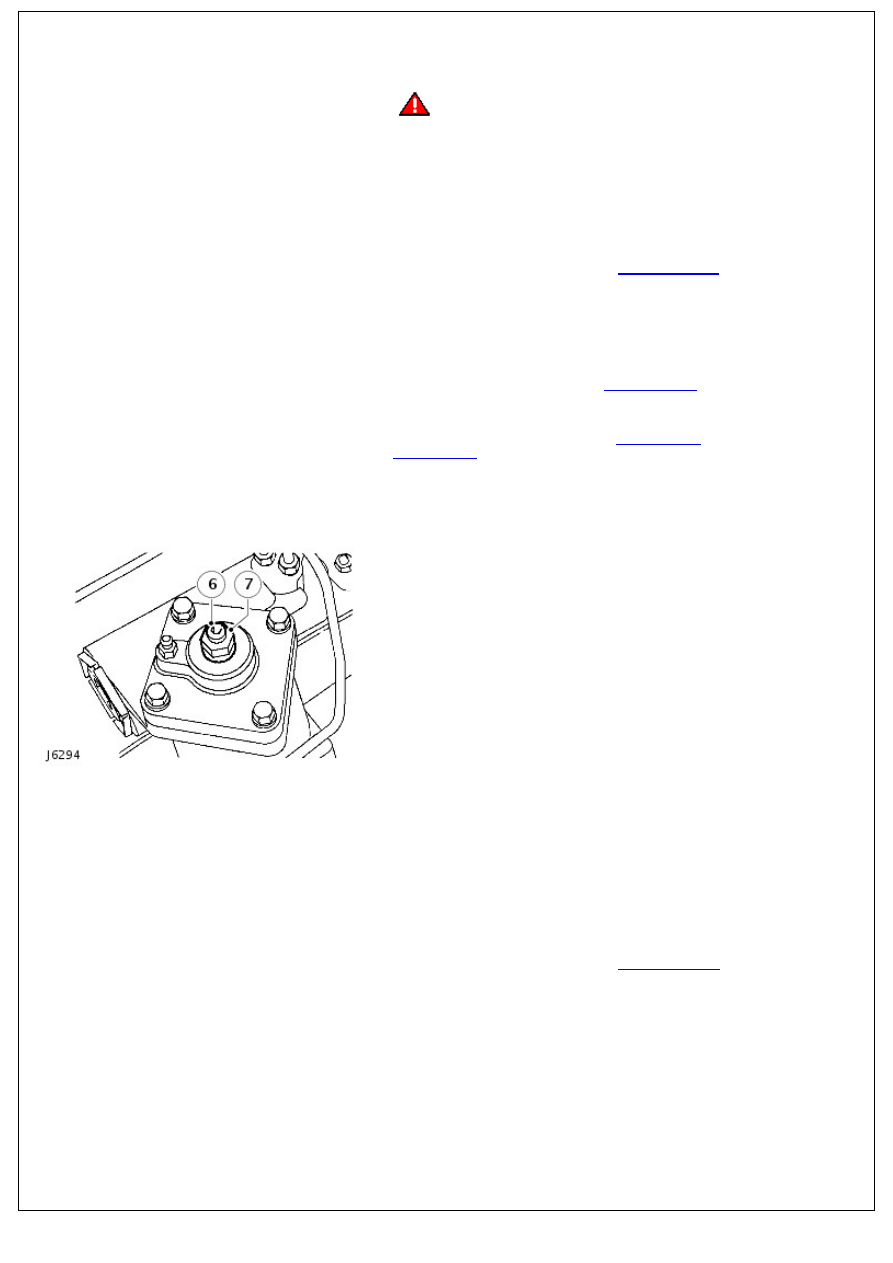
6. Adjustment is obtained by rocking the drop arm about centre
whilst an assistant slowly tightens the steering box adjuster
screw.
7. Tighten locknut when all backlash has been removed.
8. Repeat the check for backlash. If backlash exists loosen
locknut and repeat adjustment procedure.
9. Turn steering wheel lock to lock and check no tightness
exists.
10. Ensure front wheels are aligned and in straight ahead
position.
11. Adjust drag link 924 mm between ball joint centres.
12. Connect drag link and tighten to 40 Nm (30 lbf.ft).
13. Lower vehicle to ground level and remove chocks.
14. Road test vehicle
For additional information, refer to:
Steering System
(211-00
Steering System - General Information, Diagnosis and
Testing).
15. RH drive vehicles - if steering wheel is to right, drag link is
too long. If steering wheel is to left drag link is too short. LH
drive vehicles - if steering wheel is to right, drag link is too
short. If steering wheel is to left drag link is too long.
16. Adjust drag link until steering wheel points straight ahead
when vehicle is travelling in a straight line.