Jeep XJ. Manual - part 109


  Index      Jeep     Jeep XJ - service repair manual 2001 year


Search            


Content   ..  107  108  109  110   ..


Jeep XJ. Manual - part 109


(6) Reverse the removal procedures to install.

Tighten the mounting screw to 2.2 N·m (20 in. lbs.).

REAR HEADLINER

The rear headliner speakers can be serviced with-

out removing the headliner using the procedures that
follow. The headliner speaker support structure is
integral to the headliner assembly. Refer to Group 23
- Body for the headliner service procedures.

(1) Disconnect and isolate the battery negative

cable.

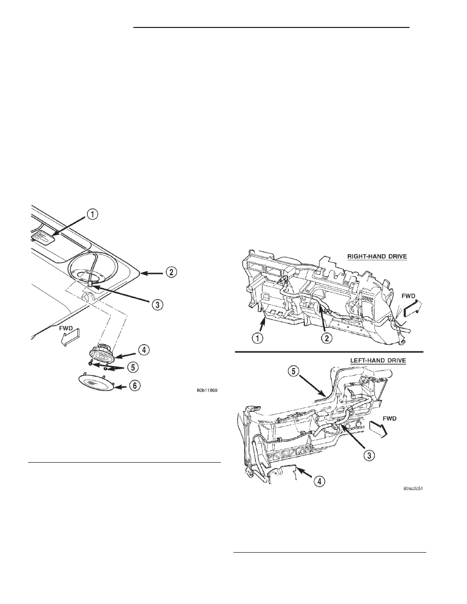
(2) Using a trim stick or another suitable wide

flat-bladed tool, gently pry around the perimeter
edge of the rear headliner speaker grille to release
the five snap retainers that secure the grille to the
headliner speaker support structure (Fig. 11).

(3) Remove the speaker grille from the headliner.
(4) Remove the two screws that secure the speaker

to the headliner speaker support structure.

(5) Lower the speaker from the headliner far

enough to access and unplug the speaker wire har-
ness connector.

(6) Remove the speaker from the headliner.
(7) Reverse the removal procedures to install.

Tighten the mounting screws to 2.2 N·m (20 in. lbs.).

ANTENNA

WARNING: ON VEHICLES EQUIPPED WITH AIR-
BAGS,

REFER

TO

GROUP

8M

-

PASSIVE

RESTRAINT SYSTEMS BEFORE ATTEMPTING ANY
STEERING

WHEEL,

STEERING

COLUMN,

OR

INSTRUMENT PANEL COMPONENT DIAGNOSIS OR
SERVICE. FAILURE TO TAKE THE PROPER PRE-
CAUTIONS COULD RESULT IN ACCIDENTAL AIR-
BAG DEPLOYMENT AND POSSIBLE PERSONAL
INJURY.

(1) Disconnect and isolate the battery negative

cable.

(2) Remove the right front fender inner splash

shield. Refer to Group 23 - Body for the procedures.

(3) Reach under the right end of the instrument

panel to unplug the antenna coaxial cable connector
(Fig. 12). Unplug the connector by pulling it apart
while twisting the metal connector halves. Do not
pull on the cable.

Fig. 11 Rear Headliner Speaker Remove/Install

1 – CARGO LAMP
2 – HEADLINER
3 – WIRE HARNESS CONNECTOR
4 – SPEAKER
5 – SCREWS
6 – SPEAKER GRILLE

Fig. 12 Antenna Cable Routing

1 – INSTRUMENT PANEL
2 – ANTENNA COAXIAL CABLE
3 – ANTENNA COAXIAL CABLE
4 – HEATER-A/C HOUSING KICK COVER
5 – INSTRUMENT PANEL

8F - 10

AUDIO SYSTEMS

XJ

REMOVAL AND INSTALLATION (Continued)

(4) Unscrew the antenna mast from the antenna

body (Fig. 13).

(5) Remove the antenna cap nut and adapter using

an antenna nut wrench (Special Tool C-4816) (Fig.
14).

(6) Lower the antenna body and cable assembly

through the top of the fender far enough to access
the antenna body by reaching up into the rear of the
right front fender wheel housing (Fig. 15).

(7) Disengage the coaxial cable grommet from the

hole in the right cowl side outer panel.

(8) Pull the coaxial cable out through the right

cowl side outer panel.

(9) Remove the antenna body and cable from the

vehicle.

(10) Reverse the removal procedures to install.

Tighten the antenna cap nut to 6.2 N·m (55 in. lbs.).
Tighten the antenna mast to 3.3 N·m (30 in. lbs.).

RADIO NOISE SUPPRESSION COMPONENTS

WARNING: ON VEHICLES EQUIPPED WITH AIR-
BAGS,

REFER

TO

GROUP

8M

-

PASSIVE

RESTRAINT SYSTEMS BEFORE ATTEMPTING ANY
STEERING

WHEEL,

STEERING

COLUMN,

OR

INSTRUMENT PANEL COMPONENT DIAGNOSIS OR
SERVICE. FAILURE TO TAKE THE PROPER PRE-
CAUTIONS COULD RESULT IN ACCIDENTAL AIR-
BAG DEPLOYMENT AND POSSIBLE PERSONAL
INJURY.

REMOVAL

ENGINE-TO-BODY GROUND STRAP

(1) Remove the screw that secures the engine-to-

body ground strap eyelet to the dash panel (Fig. 16).

Fig. 13 Antenna Mast Remove/Install - Typical

1 – ANTENNA MAST
2 – ADAPTER
3 – CAP NUT

Fig. 14 Antenna Cap Nut and Adapter Remove/

Install - Typical

1 – CAP NUT
2 – ANTENNA ADAPTER
3 – TOOL

Fig. 15 Antenna Mounting

1 – NUT
2 – MAST
3 – RIGHT FRONT FENDER
4 – ANTENNA BODY AND CABLE
5 – GROMMET
6 – ADAPTER

XJ

AUDIO SYSTEMS

8F - 11

REMOVAL AND INSTALLATION (Continued)

(2) Remove the nut that secures the engine-to-body

ground strap eyelet to the stud on the left upper rear
corner of the engine cylinder head.

(3) Remove the engine-to-body ground strap eyelet

from the stud on the left upper rear corner of the
engine cylinder head.

(4) Remove the engine-to-body ground strap from

the engine compartment.

INSTALLATION

ENGINE-TO-BODY GROUND STRAP

(1) Position the engine-to-body ground strap in the

engine compartment.

(2) Position the engine-to-body ground strap eyelet

over the stud on the left upper rear corner of the
engine cylinder head.

(3) Install and tighten the nut that secures the

engine-to-body ground strap eyelet to the stud on the
left upper rear corner of the engine cylinder head.
Tighten the nut to 27 N·m (20 ft. lbs.).

(4) Install and tighten the screw that secures the

engine-to-body ground strap eyelet to the dash panel.
Tighten the screw to 27 N·m (20 ft. lbs.).

SPECIAL TOOLS

AUDIO SYSTEMS

Fig. 16 Engine-To-Body Ground Strap Remove/

Install

1 – SCREW
2 – DASH PANEL
3 – ENGINE CYLINDER HEAD
4 – STUD
5 – NUT
6 – GROUND STRAP

Antenna Nut Wrench C-4816

8F - 12

AUDIO SYSTEMS

XJ

REMOVAL AND INSTALLATION (Continued)

HORN SYSTEMS

TABLE OF CONTENTS

page

page

DESCRIPTION AND OPERATION

HORN SYSTEM. . . . . . . . . . . . . . . . . . . . . . . . . . . 1
HORN . . . . . . . . . . . . . . . . . . . . . . . . . . . . . . . . . . 1
HORN RELAY . . . . . . . . . . . . . . . . . . . . . . . . . . . . 2
HORN SWITCH . . . . . . . . . . . . . . . . . . . . . . . . . . . 2

DIAGNOSIS AND TESTING

HORN RELAY . . . . . . . . . . . . . . . . . . . . . . . . . . . . 3

HORN SWITCH . . . . . . . . . . . . . . . . . . . . . . . . . . . 4
HORN . . . . . . . . . . . . . . . . . . . . . . . . . . . . . . . . . . 4

REMOVAL AND INSTALLATION

HORN RELAY . . . . . . . . . . . . . . . . . . . . . . . . . . . . 4
HORN . . . . . . . . . . . . . . . . . . . . . . . . . . . . . . . . . . 5

DESCRIPTION AND OPERATION

HORN SYSTEM

DESCRIPTION

A dual-note electric horn system is standard facto-

ry-installed equipment on this model. The standard
equipment horn system features one low-note horn
unit and one high-note horn unit. The horn system
uses a non-switched source of battery current so that
the system will remain functional, regardless of the
ignition switch position. The horn system includes
the following components:

• Clockspring

• Horns

• Horn relay

• Horn switch

• Remote Keyless Entry (RKE) receiver (only with

the RKE system)

Refer to Clockspring in the Description and Oper-

ation section of Group 8M - Passive Restraint Sys-
tems for more information on this component. Refer
to Remote Keyless Entry System in the Descrip-
tion and Operation section of Group 8P - Power Lock
Systems for more information on this component.
Refer to Horn/Cigar Lighter in the Contents of
Group 8W - Wiring Diagrams for complete circuit
diagrams. Following are general descriptions of the
remaining major components in the horn system.

OPERATION

The horn system is activated by a horn switch con-

cealed beneath the driver side airbag module trim
cover in the center of the steering wheel. Depressing
the center of the driver side airbag module trim cover
closes the horn switch. Closing the horn switch acti-
vates the horn relay. The activated horn relay then
switches the battery current needed to energize the
horns.

Refer to the owner’s manual in the vehicle glove

box for more information on the features, use and
operation of the horn system.

REMOTE KEYLESS ENTRY RECEIVER

The Remote Keyless Entry (RKE) receiver can also

operate the horn system. An RKE receiver is used on
this vehicle when it is equipped with the optional
RKE system. The RKE receiver controls and inte-
grates the additional electronic functions and fea-
tures

included

on

models

with

this

option. A

customer programmable feature of the RKE system
enables the RKE receiver to momentarily energize
the horn relay through a hard wired circuit as an
audible verification that the receiver has received a
valid lock request from the RKE transmitter.

Refer to Remote Keyless Entry System in the

Description and Operation section of Group 8P -
Power Lock Systems for more information on this
feature.

HORN

DESCRIPTION

The dual electromagnetic diaphragm-type horns

are standard equipment on this model. The low-note
horn is secured with a bracket to the left radiator
closure panel brace, behind the front bumper. The
high-note horn is secured with a bracket to the right
radiator

closure

panel

brace,

behind

the

front

bumper. Both horns are grounded through their
mounting brackets and receives battery feed through
its wire harness connector and circuit from the closed
contacts of the horn relay.

The horns cannot be repaired or adjusted and, if

faulty

or

damaged,

they

must

be

individually

replaced.

XJ

HORN SYSTEMS

8G - 1


Content   ..  107  108  109  110   ..