Jeep Wrangler TJ. Manual - part 599


  Index      Jeep     Jeep Wrangler TJ - service repair manual 2005 year


Search            


Content   ..  597  598  599  600   ..


Jeep Wrangler TJ. Manual - part 599


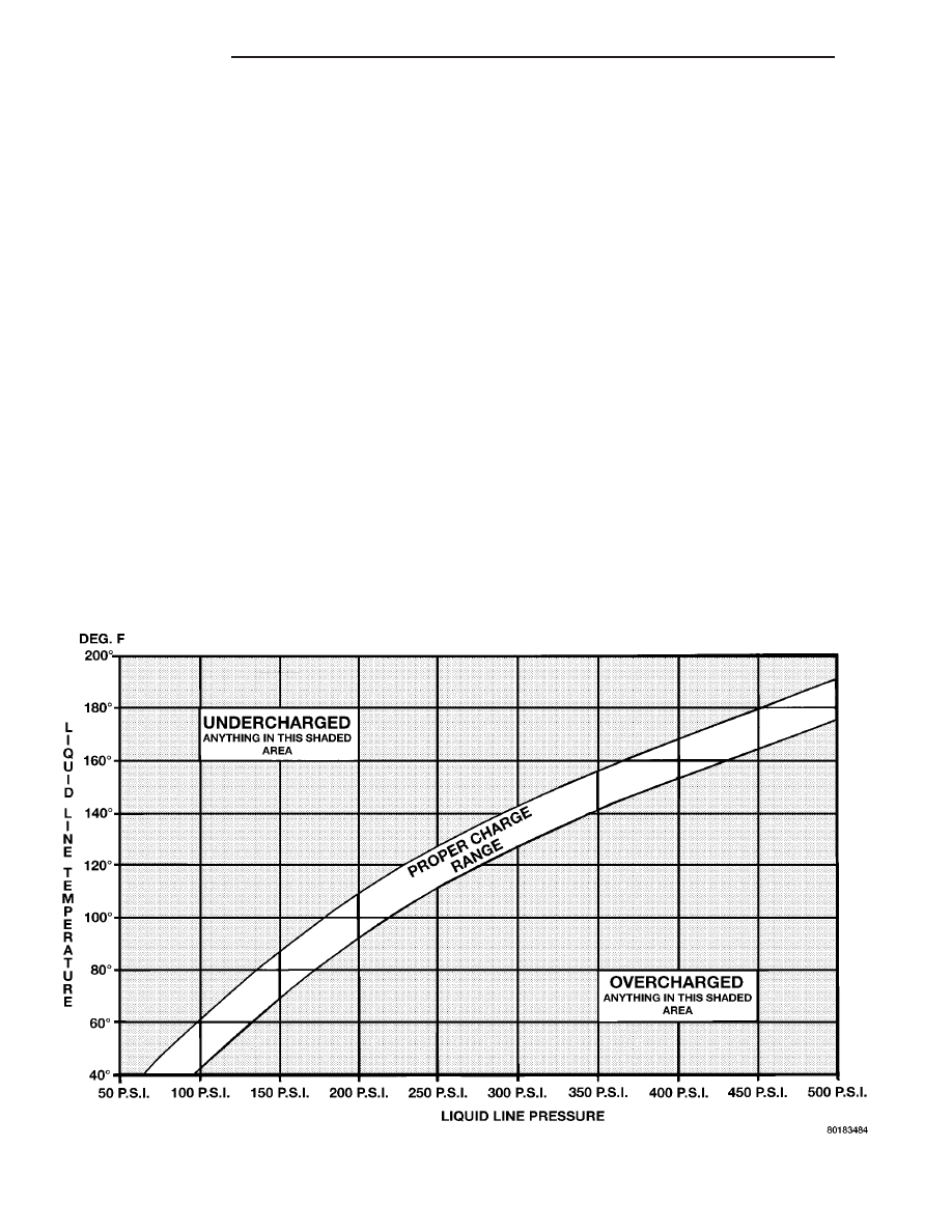
(5) Observe the liquid line (discharge) pressure

and liquid line temperature. Using the Charge Deter-
mination Chart (Fig. 3), determine whether the
refrigerant system is operating within the proper
charge range.

(a) If the refrigerant system is operating in the

undercharged area of the chart, add 0.057 kilogram
(0.125 pound or 2 ounces) of R-134a refrigerant to
the system.

(b) If the refrigerant system is operating in the

overcharged area of the chart, reclaim 0.057 kilo-
gram (0.125 pound or 2 ounces) of refrigerant from
the system.
(6) Recheck the refrigerant system charge level fol-

lowing each refrigerant level adjustment. Continue
this process until the refrigerant system readings are
in the proper charge range on the Charge Determi-
nation Chart.

REFRIGERANT SYSTEM RECOVERY

WARNING: Refer to the applicable warnings and
cautions for this system before performing the fol-
lowing operation (Refer to 24 - HEATING & AIR
CONDITIONING/PLUMBING - WARNINGS) and (Refer
to 24 - HEATING & AIR CONDITIONING/PLUMBING -
CAUTIONS). Failure to follow the warnings and cau-

tions could result in possible personal injury or
death.

A R-134a refrigerant recovery/recycling/charging

station that meets SAE Standard J2210 must be
used to recover the refrigerant from an R-134a refrig-
erant system. Refer to the operating instructions sup-
plied by the equipment manufacturer for the proper
care and use of this equipment.

REFRIGERANT SYSTEM EVACUATE

NOTE: Special effort must be used to prevent mois-
ture from entering the A/C system oil. Moisture in
the oil is very difficult to remove and will cause a
reliability problem with the A/C compressor.

If an A/C compressor designed to use R-134a refrig-

erant is left open to the atmosphere for an extended
period of time. It is recommended that the refriger-
ant oil be drained and replaced with new oil or a new
A/C compressor be used. This will eliminate the pos-
sibility of contaminating the refrigerant system.

If the refrigerant system has been open to the

atmosphere, it must be evacuated before the refriger-
ant system can be filled. Moisture and air mixed
with the refrigerant system will raise the compressor
head pressure above acceptable operating levels. This

Fig. 3 Charge Determination Chart (Ambient Test Condition 85° F)

24 - 62

PLUMBING

TJ

PLUMBING (Continued)

will reduce the performance of the A/C system and
damage the A/C compressor. Moisture will boil at
near room temperature when exposed to vacuum. A
R-134a refrigerant recovery/recycling/charging sta-
tion that meets SAE Standard J2210 must be used to
evacuate the refrigerant system. See the operating
instructions supplied by the equipment manufacturer
for proper care and use of this equipment. To evacu-
ate the refrigerant system, use the following proce-
dure:

NOTE: When connecting the service equipment
couplings to the refrigerant system service ports,
be certain that the valve of each coupling is fully
closed. This will reduce the amount of effort
required to make the connection.

(1) Connect a suitable charging station, refrigerant

recovery machine or a manifold gauge set with vac-
uum

pump

and

refrigerant

recovery

equipment

(Refer to 24 - HEATING & AIR CONDITIONING/
PLUMBING - STANDARD PROCEDURE - REFRIG-
ERANT SYSTEM SERVICE EQUIPMENT).

(2) Recover the refrigerant system (Refer to 24 -

HEATING & AIR CONDITIONING/PLUMBING -
STANDARD PROCEDURE - REFRIGERANT SYS-
TEM RECOVERY).

(3) Open the suction and discharge valves and

start the vacuum pump. The vacuum pump should
run a minimum of 45 minutes prior to charge to
eliminate all moisture within the refrigerant system.
When the suction gauge reads -88 kPa (-26 in. Hg)
vacuum or greater for 30 minutes, close all valves
and turn off vacuum pump. If the refrigerant system
fails to reach the specified vacuum, the refrigerant
system likely has a leak that must be corrected. If
the refrigerant system maintains specified vacuum
for at least 30 minutes, start the vacuum pump, open
the suction and discharge valves. Then allow the sys-
tem to evacuate an additional 10 minutes.

(4) Close all valves. Turn off and disconnect the

vacuum pump.

(5) Charge the refrigerant system (Refer to 24 -

HEATING & AIR CONDITIONING/PLUMBING -
STANDARD PROCEDURE - REFRIGERANT SYS-
TEM CHARGE).

REFRIGERANT SYSTEM CHARGE

WARNING: Refer to the applicable warnings and
cautions for this system before performing the fol-
lowing operation (Refer to 24 - HEATING & AIR
CONDITIONING/PLUMBING - WARNINGS) and (Refer
to 24 - HEATING & AIR CONDITIONING/PLUMBING -
CAUTIONS). Failure to follow the warnings and cau-
tions could result in possible personal injury or
death.

NOTE: Always refer to the A/C Underhood Specifi-
cation Label for the refrigerant fill capacity of the
vehicle being serviced.

After all refrigerant system leaks have been

repaired and the refrigerant system has been evacu-
ated, a refrigerant charge can be injected into the
system. For the proper amount of the refrigerant
charge, always refer to the A/C Underhood Specifica-
tion Label located in the engine compartment. An
R-134a refrigerant recovery/recycling/charging sta-
tion that meets SAE Standard J2210 must be used to
charge the refrigerant system with R-134a refriger-
ant. See the operating instructions supplied by the
equipment manufacturer for proper care and use of
this equipment.

CHARGING PROCEDURE

CAUTION: A small amount of refrigerant oil is
removed from the A/C system each time the refrig-
erant system is recovered and evacuated. Before
charging the A/C system, you MUST replenish any
oil lost during the recovery process. Refer the
equipment manufacturer instructions for more infor-
mation.

(1) Evacuate the refrigerant system (Refer to 24 -

HEATING & AIR CONDITIONING/PLUMBING -
STANDARD PROCEDURE - REFRIGERANT SYS-
TEM EVACUATE).

(2) A manifold gauge set and a R-134a refrigerant

recovery/recycling/charging station that meets SAE
standard J2210 should still be connected to the A/C
refrigerant system.

(3) Measure the proper amount of R-134a refriger-

ant and heat it to 52° C (125° F) with the charging
station. See the operating instructions supplied by
the equipment manufacturer for proper use of this
equipment.

(4) Open both the suction and discharge valves,

then open the charge valve to allow the heated
refrigerant to flow into the system.

(5) When the transfer of refrigerant has stopped,

close both the suction and discharge valves.

(6) If all of the refrigerant charge did not transfer

from the dispensing device, open all of the windows
in the vehicle and set the A/C-heater controls so that
the A/C compressor is engaged and the blower motor
is operating at its lowest speed setting. Run the
engine at a steady high idle (about 1400 rpm). If the
A/C compressor will not engage, test the compressor
clutch control circuit and repair as required.

(7) Open the suction valve to allow the remaining

refrigerant to transfer to the refrigerant system.

TJ

PLUMBING

24 - 63

PLUMBING (Continued)

WARNING: Take care not to open the discharge
(high pressure) valve at this time.

(8) Close the suction valve and test the A/C system

performance (Refer to 24 - HEATING & AIR CONDI-
TIONING - STANDARD PROCEDURE - A/C PER-
FORMANCE TEST).

(9) Disconnect the charging station and manifold

gauge set from the refrigerant system service ports.

(10) Install the protective caps onto the refrigerant

system service ports.

A/C COMPRESSOR

DESCRIPTION

A/C COMPRESSOR

The A/C system uses a Denso 10PA17 seven cylin-

der, reciprocating wobble plate-type A/C compressor
on all models. This A/C compressor has a fixed dis-
placement of 150 cubic centimeters (9.375 cubic
inches), and has both the suction and discharge ports
located on the cylinder head.

A label identifying the use of R-134a refrigerant is

located on the A/C compressor.

HIGH PRESSURE RELIEF VALVE

A high pressure relief valve is located on the com-

pressor manifold. This mechanical valve is designed
to vent refrigerant from the A/C system to protect
against damage to the A/C compressor and other A/C
system components, caused by a restriction in air
flow through the A/C condenser or, an overcharge of
refrigerant.

OPERATION

A/C COMPRESSOR

The A/C compressor is driven by the engine

through an electric clutch, drive pulley and belt
arrangement. The A/C compressor is lubricated by
refrigerant oil that is circulated throughout the
refrigerant system with the refrigerant.

The A/C compressor draws in low-pressure refrig-

erant vapor from the A/C evaporator through its suc-
tion port. It then compresses the refrigerant into a
high-pressure, high-temperature refrigerant vapor,
which is then pumped to the A/C condenser through
the compressor discharge port.

The A/C compressor cannot be repaired and, if

faulty or damaged, it must be replaced. The compres-
sor clutch, pulley and bearing assembly, and clutch
field coil are available for service.

HIGH PRESSURE RELIEF VALVE

The high pressure relief valve vents the A/C sys-

tem when a discharge pressure of 3445 to 4135 kPa
(500 to 600 psi) or above is reached. The high pres-
sure relief valve closes when a minimum discharge
pressure of 2756 kPa (400 psi) is reached.

The high pressure relief valve vents only enough

refrigerant to reduce the A/C system pressure, and
then re-seats itself. The majority of the refrigerant is
conserved in the A/C system. If the valve vents
refrigerant, it does not mean that the valve is faulty.

The high pressure relief valve is factory-calibrated.

The high pressure relief valve cannot be adjusted or
repaired, and must not be removed or otherwise dis-
turbed. The high pressure relief valve is only ser-
viced as a part of the A/C compressor.

DIAGNOSIS AND TESTING

A/C COMPRESSOR NOISE

When investigating an A/C system related noise,

you must first know the conditions under which the
noise occurs. These conditions include: weather, vehi-
cle speed, transmission in gear or neutral, engine
speed, engine temperature, and any other special
conditions. Noises that develop during A/C operation
can often be misleading. For example: What sounds
like a failed front engine bearing or connecting rod,
may be caused by loose bolts, nuts, mounting brack-
ets or a loose compressor clutch assembly.

Drive belts are speed sensitive. At different engine

speeds and depending upon drive belt tension, drive
belts can develop noises that are mistaken for an A/C
compressor noise. Improper drive belt tension can
cause a misleading noise when the compressor clutch
is engaged, which may not occur when the compres-
sor clutch is disengaged. Check the accessory drive
belt condition and tension as described in Cooling
before beginning this procedure.

(1) Select a quiet area for testing. Duplicate the

complaint conditions as much as possible. Switch the
compressor on and off several times to clearly iden-
tify the compressor noise. Listen to the compressor
while the clutch is engaged and disengaged. Probe
the compressor with an engine stethoscope or a long
screwdriver with the handle held to your ear to bet-
ter localize the source of the noise.

(2) Loosen all of the compressor mounting hard-

ware and retighten. Tighten the compressor clutch
mounting nut. Be certain that the clutch coil is
mounted securely to the compressor, and that the
clutch plate and pulley are properly aligned and have
the correct air gap (Refer to 24 - HEATING & AIR
CONDITIONING/CONTROLS/A/C

COMPRESSOR

CLUTCH - INSTALLATION).

24 - 64

PLUMBING

TJ

PLUMBING (Continued)

(3) To duplicate a high-ambient temperature condi-

tion (high head pressure), restrict the air flow
through the condenser. Install a manifold gauge set
to be certain that the discharge pressure does not
exceed 2760 kPa (400 psi).

(4) Check the refrigerant system plumbing for

incorrect routing, rubbing or interference, which can
cause unusual noises. Also check the refrigerant lines
for kinks or sharp bends that will restrict refrigerant
flow, which can cause noises (Refer to 24 - HEATING
& AIR CONDITIONING/PLUMBING - DESCRIP-
TION - REFRIGERANT LINES).

(5) If the noise is from opening and closing of the

high pressure relief valve, recover, evacuate and
recharge the refrigerant system (Refer to 24 - HEAT-
ING & AIR CONDITIONING/PLUMBING - STAN-
DARD PROCEDURE - REFRIGERANT SYSTEM
RECOVERY), (Refer to 24 - HEATING & AIR CON-
DITIONING/PLUMBING

-

STANDARD

PROCE-

DURE - REFRIGERANT SYSTEM EVACUATE) and
(Refer to 24 - HEATING & AIR CONDITIONING/
PLUMBING - STANDARD PROCEDURE - REFRIG-
ERANT SYSTEM CHARGE).

(6) If the noise is from liquid slugging on the suc-

tion line, replace the accumulator (Refer to 24 -
HEATING & AIR CONDITIONING/PLUMBING/AC-
CUMULATOR - REMOVAL) and check the refriger-
ant oil level and the refrigerant system charge (Refer
to 24 - HEATING & AIR CONDITIONING/PLUMB-
ING/REFRIGERANT OIL - STANDARD PROCE-
DURE - REFRIGERANT SYSTEM OIL LEVEL).

(7) If the liquid slugging condition continues fol-

lowing accumulator replacement, replace the A/C
compressor and repeat Step 1.

REMOVAL

2.4L ENGINE

WARNING: Refer to the applicable warnings and
cautions for this system before performing the fol-
lowing operation (Refer to 24 - HEATING & AIR
CONDITIONING/PLUMBING - WARNINGS) and (Refer
to 24 - HEATING & AIR CONDITIONING/PLUMBING -
CAUTIONS). Failure to follow the warnings and cau-
tions could result in possible personal injury or
death.

NOTE: The A/C compressor may be removed and
repositioned without disconnecting the refrigerant
lines or discharging the refrigerant system. Dis-
charging is not necessary if servicing the A/C
clutch, clutch field coil or the engine.

(1) Recover the refrigerant from the refrigerant

system (Refer to 24 - HEATING & AIR CONDITION-
ING/PLUMBING

-

STANDARD

PROCEDURE

-

REFRIGERANT RECOVERY).

(2) Disconnect and isolate the negative battery

cable.

(3) Remove the accessory drive belt (Refer to 7 -

COOLING/ACCESSORY

DRIVE/DRIVE

BELTS

-

REMOVAL).

(4) Disconnect the wire harness connector from the

A/C clutch field coil.

(5) Remove the nuts that secure the A/C suction

and discharge lines to the A/C compressor and
remove and discard the O-ring seals (Fig. 4).

(6) Install plugs in, or tape over all of the opened

refrigerant line fittings and compressor ports.

Fig. 4 A/C Compressor Refrigerant Lines - 2.4L

Engine

1 - NUT
2 - A/C DISCHARGE LINE
3 - WIRE HARNESS CONNECTOR
4 - A/C PRESSURE TRANSDUCER
5 - NUT
6 - ACCUMULATOR
7 - A/C SUCTION LINE (FRONT SECTION)
8 - NUT (4)
9 - A/C SUCTION LINE (REAR SECTION)
10 - SECONDARY RETAINING CLIP
11 - A/C CONDENSER
12 - A/C COMPRESSOR

TJ

PLUMBING

24 - 65

A/C COMPRESSOR (Continued)


Content   ..  597  598  599  600   ..