Jeep Wrangler TJ. Manual - part 322


  Index      Jeep     Jeep Wrangler TJ - service repair manual 2005 year


Search            


Content   ..  320  321  322  323   ..


Jeep Wrangler TJ. Manual - part 322


opening, and are accessed from behind the rear seat.
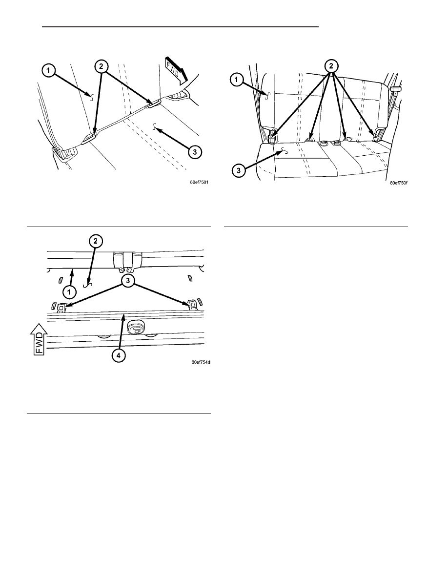
The upper tether anchors for the rear seat are avail-
able for individual service replacement. The four
fixed lower anchors are integral to the rear seat back
frame and are accessed from the front of the rear
seat, where the seat back meets the seat cushion.
The two inboard lower anchors are constructed from
round steel bar stock that is formed into a U-shape,
then securely welded at each end to the rear seat
back frame. The two outboard lower anchors are
machined steel pins that are secured between the
two seat back hinge plates above the pivot pin on
each outboard side of the rear seat back frame. These
lower anchors cannot be adjusted or repaired and, if

faulty or damaged, they must be replaced as a unit
with the rear seat back frame.

WARNING: DURING AND FOLLOWING ANY SEAT
BELT OR CHILD RESTRAINT ANCHOR SERVICE,
CAREFULLY INSPECT ALL SEAT BELTS, BUCKLES,
MOUNTING HARDWARE, RETRACTORS, TETHER
STRAPS, AND ANCHORS FOR PROPER INSTALLA-
TION, OPERATION, OR DAMAGE. REPLACE ANY
BELT

THAT

IS

CUT,

FRAYED,

OR

TORN.

STRAIGHTEN

ANY

BELT

THAT

IS

TWISTED.

TIGHTEN ANY LOOSE FASTENERS. REPLACE ANY
BELT THAT HAS A DAMAGED OR INOPERATIVE
BUCKLE OR RETRACTOR. REPLACE ANY BELT
THAT HAS A BENT OR DAMAGED LATCH PLATE
OR

ANCHOR

PLATE.

REPLACE

ANY

CHILD

RESTRAINT ANCHOR OR THE UNIT TO WHICH THE
ANCHOR IS INTEGRAL THAT HAS BEEN BENT OR
DAMAGED. NEVER ATTEMPT TO REPAIR A SEAT
BELT

OR

CHILD

RESTRAINT

COMPONENT.

ALWAYS REPLACE DAMAGED OR FAULTY SEAT
BELT AND CHILD RESTRAINT COMPONENTS WITH
THE CORRECT, NEW AND UNUSED REPLACEMENT
PARTS LISTED IN THE DAIMLERCHRYSLER MOPAR
PARTS CATALOG.

OPERATION

See the owner’s manual in the vehicle glove box for

more information on the proper use of all of the fac-
tory-installed child restraint anchors.

REMOVAL

The following procedure applies only to the rear

seat upper child tether anchors used on models
equipped with an optional rear seat. The child

Fig. 11 Front Passenger Seat Lower Anchors

1 - SEAT BACK
2 - LOWER ANCHOR (2)
3 - SEAT CUSHION

Fig. 12 Rear Seat Upper Anchors

1 - REAR SEAT
2 - REAR CARGO FLOOR
3 - UPPER ANCHOR (2)
4 - TAILGATE OPENING SILL

Fig. 13 Rear Seat Lower Anchors

1 - SEAT BACK
2 - LOWER ANCHOR (4)
3 - SEAT CUSHION

TJ

RESTRAINTS

8O - 13

CHILD RESTRAINT ANCHOR (Continued)

restraint anchors used in this model in all other loca-
tions are integral to other components and cannot be
serviced separately.

WARNING:

TO

AVOID

PERSONAL

INJURY

OR

DEATH, DURING AND FOLLOWING ANY SEAT BELT
OR CHILD RESTRAINT ANCHOR SERVICE, CARE-
FULLY INSPECT ALL SEAT

BELTS,

BUCKLES,

MOUNTING HARDWARE, RETRACTORS, TETHER
STRAPS, AND ANCHORS FOR PROPER INSTALLA-
TION, OPERATION, OR DAMAGE. REPLACE ANY
BELT

THAT

IS

CUT,

FRAYED,

OR

TORN.

STRAIGHTEN

ANY

BELT

THAT

IS

TWISTED.

TIGHTEN ANY LOOSE FASTENERS. REPLACE ANY
BELT THAT HAS A DAMAGED OR INOPERATIVE
BUCKLE OR RETRACTOR. REPLACE ANY BELT
THAT HAS A BENT OR DAMAGED LATCH PLATE
OR

ANCHOR

PLATE.

REPLACE

ANY

CHILD

RESTRAINT ANCHOR OR THE UNIT TO WHICH THE
ANCHOR IS INTEGRAL THAT HAS BEEN BENT OR
DAMAGED. NEVER ATTEMPT TO REPAIR A SEAT
BELT

OR

CHILD

RESTRAINT

COMPONENT.

ALWAYS REPLACE DAMAGED OR FAULTY SEAT
BELT AND CHILD RESTRAINT COMPONENTS WITH
THE CORRECT, NEW AND UNUSED REPLACEMENT
PARTS LISTED IN THE DAIMLERCHRYSLER MOPAR
PARTS CATALOG.

(1) Remove the screw that secures the upper child

restraint tether anchor to the rear cargo floor panel
just forward of the tailgate opening sill (Fig. 14).

(2) Remove the upper tether anchor from the rear

cargo floor panel.

INSTALLATION

The following procedure applies only to the rear

seat upper child tether anchors used on models
equipped with an optional rear seat. The child
restraint anchors used in this model in all other loca-
tions are integral to other components and cannot be
serviced separately.

WARNING:

TO

AVOID

PERSONAL

INJURY

OR

DEATH, DURING AND FOLLOWING ANY SEAT BELT
OR CHILD RESTRAINT ANCHOR SERVICE, CARE-
FULLY INSPECT ALL SEAT

BELTS,

BUCKLES,

MOUNTING HARDWARE, RETRACTORS, TETHER
STRAPS, AND ANCHORS FOR PROPER INSTALLA-
TION, OPERATION, OR DAMAGE. REPLACE ANY
BELT

THAT

IS

CUT,

FRAYED,

OR

TORN.

STRAIGHTEN

ANY

BELT

THAT

IS

TWISTED.

TIGHTEN ANY LOOSE FASTENERS. REPLACE ANY
BELT THAT HAS A DAMAGED OR INOPERATIVE
BUCKLE OR RETRACTOR. REPLACE ANY BELT
THAT HAS A BENT OR DAMAGED LATCH PLATE
OR

ANCHOR

PLATE.

REPLACE

ANY

CHILD

RESTRAINT ANCHOR OR THE UNIT TO WHICH THE

ANCHOR IS INTEGRAL THAT HAS BEEN BENT OR
DAMAGED. NEVER ATTEMPT TO REPAIR A SEAT
BELT

OR

CHILD

RESTRAINT

COMPONENT.

ALWAYS REPLACE DAMAGED OR FAULTY SEAT
BELT AND CHILD RESTRAINT COMPONENTS WITH
THE CORRECT, NEW AND UNUSED REPLACEMENT
PARTS LISTED IN THE DAIMLERCHRYSLER MOPAR
PARTS CATALOG.

(1) Position the upper tether anchor onto the rear

cargo floor panel (Fig. 14).

(2) Install and tighten the screw that secures the

upper tether anchor to the rear cargo floor panel just
forward of the tailgate opening sill. Tighten the
screw to 26 N·m (19 ft. lbs.).

CLOCKSPRING

DESCRIPTION

The clockspring assembly is secured with two inte-

gral plastic latches onto the steering column lock
housing near the top of the steering column behind
the steering wheel (Fig. 15). The clockspring consists
of a flat, round molded plastic case with a stubby tail
that hangs below the steering column (Fig. 16). The
tail contains two connector receptacles that face
toward the instrument panel. Within the plastic case
is a spool-like molded plastic rotor with a large
exposed hub. The upper surface of the rotor hub has
a large center hole, two large flats, and four short

Fig. 14 Rear Upper Tether Anchor Remove/Install

1 - SCREW (2)
2 - FLOOR PANEL
3 - ANCHOR (2)

8O - 14

RESTRAINTS

TJ

CHILD RESTRAINT ANCHOR (Continued)

pigtail wires with connectors that face toward the
steering wheel.

The lower surface of the rotor hub has a molded

plastic turn signal cancel cam consisting of two lobes
that are molded into the rotor. Within the plastic
case and wound around the rotor spool is a long rib-
bon-like tape that consists of several thin copper wire
leads sandwiched between two thin plastic mem-
branes. The outer end of the tape terminates at the
connector receptacles that face the instrument panel,

while the inner end of the tape terminates at the pig-
tail wires on the hub of the clockspring rotor that
face the steering wheel.

Service replacement clocksprings are shipped pre-

centered and with a molded plastic locking pin that
snaps into a receptacle in the rotor and has a tab
that is engaged between two ribs on the upper sur-
face of the clockspring case. The locking pin secures
the centered clockspring rotor to the clockspring case
during shipment, but the locking pin must be
removed from the clockspring after it is installed on
the steering column. (Refer to 8 - ELECTRICAL/RE-
STRAINTS/CLOCKSPRING - STANDARD PROCE-
DURE - CLOCKSPRING CENTERING).

The clockspring cannot be repaired. If the clock-

spring is faulty, damaged, or if the driver airbag has
been deployed, the clockspring must be replaced.

OPERATION

The clockspring is a mechanical electrical circuit

component that is used to provide continuous electri-
cal continuity between the fixed body wire harness
on the steering column and the electrical components
mounted on or in the rotating steering wheel. On this
model the rotating electrical components include the
driver airbag, the horn switch, and the speed control
switches if the vehicle is so equipped. The clock-
spring case is positioned and secured to the upper
steering column housing near the top of the steering
column. The connector receptacles on the tail of the
fixed clockspring case connect the clockspring to the
vehicle electrical system through two take outs with
connectors from the body wire harness.

The clockspring rotor is movable and is keyed by

two flats molded into the rotor hub to two flats that
are cast into the lower surface of the steering wheel
armature. The two lobes on the turn signal cancel
cam on the lower surface of the clockspring rotor hub
contact a turn signal cancel actuator of the multi-
function switch to provide automatic turn signal can-
cellation. The pigtail wires on the upper surface of
the clockspring rotor connect the clockspring to the
driver airbag, the horn switch, and the two speed
control switches if the vehicle is so equipped.

Like the clockspring in a timepiece, the clockspring

tape has travel limits and can be damaged by being
wound too tightly during full stop-to-stop steering
wheel rotation. To prevent this from occurring, the
clockspring is centered when it is installed on the
steering column. Centering the clockspring indexes
the clockspring tape to the movable steering compo-
nents so that the tape can operate within its
designed travel limits. However, if the clockspring is
removed from the steering column or if the steering
shaft is disconnected from the steering gear, the
clockspring spool can change position relative to the

Fig. 15 Clockspring

1 - CASE
2 - LOCKING PIN
3 - ROTOR
4 - ROTOR FLAT (2)
5 - CLOCKSPRING PIGTAIL WIRES (NOT SHOWN)

Fig. 16 Turn Signal Cancel Cam

1 - AIRBAG PIGTAIL
2 - LOCKING PIN
3 - LATCH (2)
4 - CANCEL CAM
5 - LOWER CONNECTOR RECEPTACLE (2)
6 - HORN SWITCH FEED PIGTAIL
7 - SPEED CONTROL SWITCH PIGTAIL (2)

TJ

RESTRAINTS

8O - 15

CLOCKSPRING (Continued)

movable steering components. The clockspring must
be re-centered following completion of this service or
the tape may be damaged.

Service replacement clocksprings are shipped pre-

centered and with a plastic locking pin installed.
This locking pin should not be disengaged until the
clockspring has been installed on the steering col-
umn. If the locking pin is removed or damaged before
the clockspring is installed on a steering column, the
clockspring centering procedure must be performed.
(Refer to 8 - ELECTRICAL/RESTRAINTS/CLOCK-
SPRING - STANDARD PROCEDURE - CLOCK-
SPRING CENTERING).

STANDARD PROCEDURE - CLOCKSPRING
CENTERING

The clockspring is designed to wind and unwind

when the steering wheel is rotated, but is only
designed to rotate the same number of turns (about
five complete rotations) as the steering wheel can be
turned from stop to stop. Centering the clockspring
indexes the clockspring tape to other steering compo-
nents so that it can operate within its designed
travel limits. The rotor of a centered clockspring can
be rotated two and one-half turns in either direction
from the centered position, without damaging the
clockspring tape.

However, if the clockspring is removed for service

or if the steering column is disconnected from the
steering gear, the clockspring tape can change posi-
tion relative to the other steering components. The
clockspring must then be re-centered following com-
pletion of such service or the clockspring tape may be
damaged.

Service

replacement

clocksprings

are

shipped pre-centered, with a plastic locking pin
installed (Fig. 17). This locking pin should not be
removed until the clockspring has been installed on
the steering column. If the locking pin is removed
before the clockspring is installed on a steering col-
umn, the clockspring centering procedure must be
performed.

WARNING:

TO

AVOID

PERSONAL

INJURY

OR

DEATH, ON VEHICLES EQUIPPED WITH AIRBAGS,
DISABLE THE SUPPLEMENTAL RESTRAINT SYS-
TEM

BEFORE

ATTEMPTING

ANY

STEERING

WHEEL, STEERING COLUMN, AIRBAG, OR INSTRU-
MENT PANEL COMPONENT DIAGNOSIS OR SER-
VICE. DISCONNECT AND ISOLATE THE BATTERY
NEGATIVE (GROUND) CABLE, THEN WAIT TWO
MINUTES FOR THE SYSTEM CAPACITOR TO DIS-
CHARGE BEFORE PERFORMING FURTHER DIAG-
NOSIS OR SERVICE. THIS IS THE ONLY SURE WAY
TO DISABLE THE SUPPLEMENTAL RESTRAINT
SYSTEM. FAILURE TO TAKE THE PROPER PRE-

CAUTIONS COULD RESULT IN ACCIDENTAL AIR-
BAG DEPLOYMENT.

NOTE: Before starting this procedure, be certain to
turn the steering wheel until the front wheels are in
the straight-ahead position.

(1) Place the front wheels in the straight-ahead

position.

(2) Remove the clockspring from the steering col-

umn. (Refer to 8 - ELECTRICAL/RESTRAINTS/
CLOCKSPRING - REMOVAL).

(3) Rotate the clockspring rotor clockwise to the

end of its travel. Do not apply excessive torque.

(4) From the end of the clockwise travel, rotate the

rotor about two and one-half turns counterclockwise,
until the rotor flats are horizontal. If the clockspring
pigtail wires are not oriented towards the bottom of
the clockspring, rotate the rotor another one-half
turn in the counterclockwise direction. The clock-
spring is now centered.

(5) Lock the clockspring rotor to the clockspring

case to maintain clockspring centering until it is
reinstalled on the steering column.

(6) The front wheels should still be in the straight-

ahead position. Reinstall the clockspring onto the
steering column. (Refer to 8 - ELECTRICAL/RE-
STRAINTS/CLOCKSPRING - INSTALLATION).

REMOVAL

The clockspring cannot be repaired. It must be

replaced if faulty or damaged, or if the driver airbag
has been deployed.

Fig. 17 Clockspring

1 - CASE
2 - LOCKING PIN
3 - ROTOR
4 - ROTOR FLAT (2)
5 - CLOCKSPRING PIGTAIL WIRES (NOT SHOWN)

8O - 16

RESTRAINTS

TJ

CLOCKSPRING (Continued)


Content   ..  320  321  322  323   ..