Jeep Wrangler TJ. Manual - part 249


  Index      Jeep     Jeep Wrangler TJ - service repair manual 2005 year


Search            


Content   ..  247  248  249  250   ..


Jeep Wrangler TJ. Manual - part 249


(7) Remove caliper mounting bolt bushings and

boots (Fig. 16).

CLEANING

Clean the caliper components with clean brake

fluid or brake clean only. Wipe the caliper and piston
dry with lint free towels or use low pressure com-
pressed air.

CAUTION: Do not use gasoline, kerosene, paint
thinner, or similar solvents. These products may
leave a residue that could damage the piston and
seal.

INSPECTION

The piston is made from a phenolic resin (plastic

material) and should be smooth and clean.

The piston must be replaced if cracked or scored.

Do not attempt to restore a scored piston surface by
sanding or polishing.

CAUTION: If the caliper piston is replaced, install
the same type of piston in the caliper. Never inter-
change phenolic resin and steel caliper pistons.
The pistons, seals, seal grooves, caliper bore and
piston tolerances are different.

The bore can be lightly polished with a brake

hone to remove very minor surface imperfections
(Fig. 17). The caliper should be replaced if the bore is
severely corroded, rusted, scored, or if polishing
would increase bore diameter more than 0.025 mm
(0.001 inch).

ASSEMBLY

CAUTION: Dirt, oil, and solvents can damage cali-
per seals. Insure assembly area is clean and dry.

(1) Lubricate caliper piston bore, new piston seal

and piston with clean brake fluid.

(2) Lubricate caliper bushings and interior of

bushing boots with silicone grease.

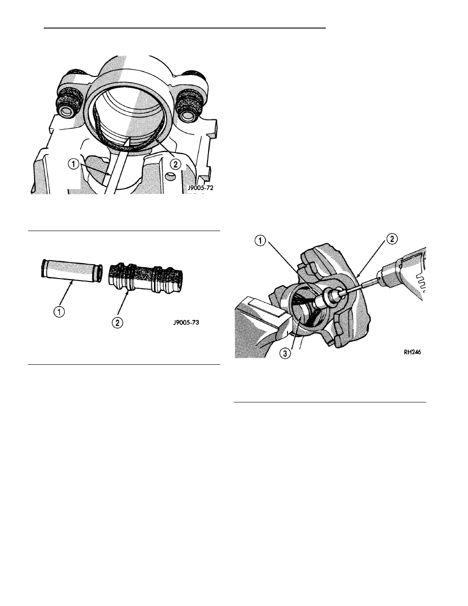
Fig. 15 Piston Seal Removal

1 - REMOVE SEAL WITH WOOD PENCIL OR SIMILAR TOOL
2 - PISTON SEAL

Fig. 16 Mounting Bolt Bushing And Boot

1 - CALIPER SLIDE BUSHING
2 - BOOT

Fig. 17 Polishing Piston Bore

1 - SPECIAL HONE
2 - CALIPER
3 - PISTON BORE

TJ

BRAKES - BASE

5 - 13

DISC BRAKE CALIPERS (Continued)

(3) Install bushing boots in caliper, then insert

bushing into boot and push bushing into place (Fig.
18).

(4) Install new piston seal into seal groove with

finger (Fig. 19).

(5) Install new dust boot on caliper piston and seat

boot in piston groove (Fig. 20).

(6) Press piston into caliper bore by hand, use a

turn and push motion to work piston into seal (Fig.
21).

(7) Press caliper piston to bottom of bore.
(8) Seat dust boot in caliper with Installer Tool

C-4842 and Tool Handle C-4171 (Fig. 22).

(9) Replace caliper bleed screw if removed.

Fig. 18 Bushings And Boots Installation

1 - BUSHING
2 - BOOT

Fig. 19 Piston Seal Installation

1 - SEAL GROOVE
2 - PISTON SEAL

Fig. 20 Dust Boot On Piston

1 - PISTON
2 - DUST BOOT

Fig. 21 Caliper Piston Installation

1 - PISTON
2 - BOOT

5 - 14

BRAKES - BASE

TJ

DISC BRAKE CALIPERS (Continued)

INSTALLATION

INSTALLATION - FRONT

(1) Clean brake shoe mounting ledges with wire

brush and apply light coat of Mopar multi-mileage
grease to surfaces (Fig. 23).

(2) Install caliper by position notches at lower end

of brake shoes on bottom mounting ledge. Then

rotate caliper over rotor and seat notches at upper
end of shoes on top mounting ledge (Fig. 24).

(3) Coat

caliper

mounting

bolts

with

silicone

grease. Then install and tighten bolts to 15 N·m (11
ft. lbs.).

CAUTION: If new caliper bolts are being installed,
or if the original reason for repair was a drag/pull
condition, check caliper bolt length before proceed-
ing. Bolts must not have a shank length greater
than 67.6 mm (2.66 in.) (Fig. 25).

Fig. 22 Piston Dust Boot Installation

1 - HANDLE C-4171
2 - INSTALLER C-4842
3 - DUST BOOT

Fig. 23 Caliper Lubrication Points

1 - BUSHINGS
2 - CALIPER MOUNTING BOLTS
3 - MOUNTING LEDGES

Fig. 24 Caliper Installation

1 - TOP LEDGE
2 - BRAKESHOE TAB ON LEDGE OUTER SURFACE
3 - LEDGE SEATED IN BRAKESHOE NOTCH
4 - BOTTOM LEDGE

Fig. 25 Mounting Bolt Dimensions

1 - 67 mm (± 0.6 mm) 2.637 in. (± 0.0236 in.)
2 - 22 mm (0.866 in.) THREAD LENGTH
3 - CALIPER BOLT

TJ

BRAKES - BASE

5 - 15

DISC BRAKE CALIPERS (Continued)

(4) Install brake hose to caliper with new seal

washers and tighten fitting bolt to 31 N·m (23 ft.
lbs.).

CAUTION: Verify brake hose is not twisted or
kinked before tightening fitting bolt.

(5) Bleed base brake system. (Refer to 5 - BRAKES

- STANDARD PROCEDURE).

(6) Install wheel and tire assemblies. (Refer to 22 -

TIRES/WHEELS/WHEELS - STANDARD PROCE-
DURE).

(7) Remove supports and lower vehicle.
(8) Verify firm pedal before moving vehicle.

INSTALLATION - REAR

(1) Install the brake pads if removed.
(2) Lubricate ant-rattle clips for the disc brake

pads (Fig. 26).

(3) Install caliper to the caliper adapter.
(4) Coat the caliper mounting slide pin bolts with

silicone grease. Then install and tighten the bolts to
15 N·m (11 ft. lbs.).

(5) Install the brake hose banjo bolt if removed

(Fig. 27).

(6) Install the brake hose to the caliper with new

seal washers and tighten fitting bolt to 31 N·m (23
ft. lbs.).

CAUTION: Verify brake hose is not twisted or
kinked before tightening fitting bolt.

(7) Remove the prop rod from the vehicle.
(8) Bleed the base brake system, (Refer to 5 -

BRAKES - STANDARD PROCEDURE) OR (Refer to
5 - BRAKES - STANDARD PROCEDURE).

(9) Install the wheel and tire assemblies (Refer to

22 - TIRES/WHEELS/WHEELS - STANDARD PRO-
CEDURE).

(10) Remove the supports and lower the vehicle.
(11) Verify a firm pedal before moving the vehicle.

BRAKE PADS/SHOES

REMOVAL

REMOVAL - FRONT PADS

(1) Raise and support vehicle.
(2) Remove wheel and tire assembly.
(3) Remove caliper. (Refer to 5 - BRAKES/HY-

DRAULIC/MECHANICAL/DISC BRAKE CALIPERS
- REMOVAL).

(4) Pressing one end of outboard shoe inward to

disengage shoe lug. Then rotate shoe upward until
retainer spring clears caliper. Press opposite end of
shoe inward to disengage shoe lug and rotate shoe up
and out of caliper (Fig. 28).

(5) Grasp ends of inboard shoe and tilt shoe out-

ward to release springs from caliper piston (Fig. 29)
and remove shoe from caliper.

NOTE: If original brake shoes will be used, keep
them in sets left and right. They are not inter-
changeable.

(6) Secure caliper to nearby suspension part with

wire. Do not allow brake hose to support caliper
weight.

(7) Wipe caliper off with shop rags or towels.

Fig. 26 ANTI-RATTLE CLIPS

1 - ROTOR
2 - ANTI-RATTLE CLIPS

Fig. 27 CALIPER INSTALLED

1 - CALIPER MOUNTING BOLTS
2 - CALIPER SLIDES

5 - 16

BRAKES - BASE

TJ

DISC BRAKE CALIPERS (Continued)


Content   ..  247  248  249  250   ..