Jeep Wrangler TJ. Manual - part 211
(8) Install drag link and tie rod and tighten nut to
torque specification
(9) Install steering damper to the axle bracket and
tighten nut to torque specification.
(10) Install brake components.
(11) Install propeller shaft.
(12) Remove lift from the axle and lower vehicle.
(13) Tighten upper and lower control arm nuts to
torque specification.
(14) Tighten track bar bolt at the axle bracket to
torque specification.
(15) Check the front wheel alignment.
ADJUSTMENTS
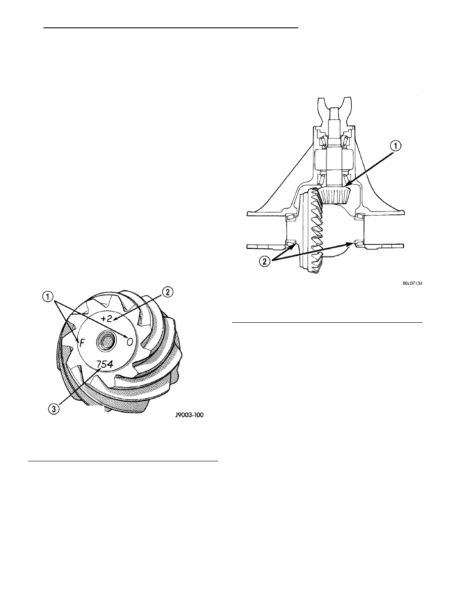
Ring and pinion gears are supplied as matched
sets only. The identifying numbers for the ring and
pinion gear are etched/marked onto each gear (Fig.
8). A plus (+) number, minus (–) number or zero (0) is
etched/marked on the pinion gear. This number is
the amount (in thousandths of an inch) the depth
varies from the standard depth setting of a pinion
etched/marked with a (0). The standard setting from
the center line of the ring gear to the back face of the
pinion is 92.08 mm (3.625 in.). The standard depth
provides the best gear tooth contact pattern.
Compensation
for
pinion
depth
variance
is
achieved with a select shim/oil slinger. The shims are
placed between the rear pinion bearing and the pin-
ion gear head (Fig. 9).
If a new gear set is being installed, note the depth
variance etched into both the original and replace-
ment pinion. Add or subtract this number from the
thickness of the original depth shim/oil slinger to
compensate for the difference in the depth variances.
Refer to the Pinion Gear Depth Variance chart.
Note where Old and New Pinion Marking columns
intersect.
Intersecting
figure
represents
plus
or
minus the amount needed.
Note the etched number on the face of the pinion
gear head (–1, –2, 0, +1, +2, etc.). The numbers rep-
resent thousands of an inch deviation from the stan-
dard. If the number is negative, add that value to the
required thickness of the depth shims. If the number
is positive, subtract that value from the thickness of
the depth shim. If the number is 0 no change is nec-
essary.
Fig. 8 PINION GEAR ID NUMBERS
1 - PRODUCTION NUMBERS
2 - PINION GEAR DEPTH VARIANCE
3 - GEAR MATCHING NUMBER
Fig. 9 SHIM LOCATIONS
1 - PINION GEAR DEPTH SHIM/OIL SLINGER
2 - DIFFERENTIAL BEARING SHIM
TJ
FRONT AXLE - 181FBI
3 - 21
FRONT AXLE - 181FBI (Continued)