Jeep Wrangler TJ. Manual - part 203


  Index      Jeep     Jeep Wrangler TJ - service repair manual 2005 year


Search            


Content   ..  201  202  203  204   ..


Jeep Wrangler TJ. Manual - part 203


OPERATION

The hub/bearing assembly is mounted to the steer-

ing knuckle and is retained by three mounting bolts
accessible from the back of the steering knuckle. The
hub/bearing unit is not serviceable and must be
replaced as an assembly if the bearing or the hub is
determined to be defective.

REMOVAL

(1) Raise and support the vehicle.
(2) Remove the wheel and tire assembly.
(3) Remove the brake caliper, rotor and ABS wheel

speed sensor, (Refer to 5 - BRAKES/HYDRAULIC/
MECHANICAL/ROTORS - REMOVAL).

(4) Remove the cotter pin, nut retainer and axle

hub nut (Fig. 3).

(5) Remove the hub bearing mounting bolts from

the back of the steering knuckle. Remove hub bear-
ing from the steering knuckle and off the axle shaft.

INSTALLATION

(1) Install the hub bearing and brake dust shield

to the knuckle.

(2) Install the hub bearing to knuckle bolts and

tighten to 102 N·m (75 ft. lbs.).

(3) Install the hub washer and nut. Tighten the

hub nut to 237 N·m (175 ft. lbs.). Install the nut
retainer and a new cotter pin.

(4) Install the brake rotor, caliper and ABS wheel

speed sensor, (Refer to 5 - BRAKES/HYDRAULIC/
MECHANICAL/ROTORS - INSTALLATION).

(5) Install the wheel and tire assembly. (Refer to

22 - TIRES/WHEELS/WHEELS - STANDARD PRO-
CEDURE).

(6) Remove support and lower the vehicle.

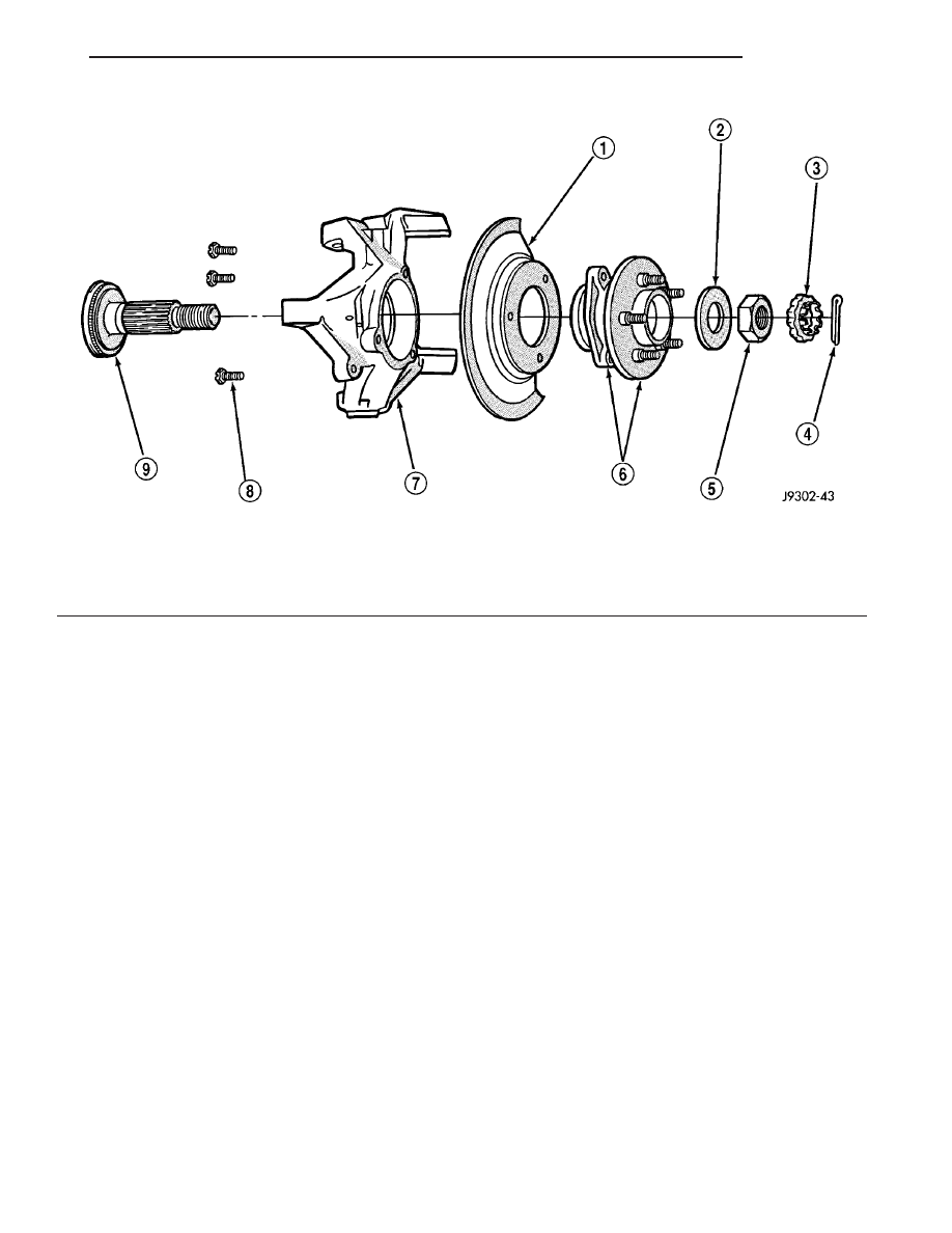
Fig. 3 Hub Bearing & Knuckle

1 - BRAKE SHIELD
2 - WASHER
3 - RETAINER
4 - COTTER PIN
5 - NUT

6 - HUB AND BEARING ASSEMBLY
7 - STEERING KNUCKLE
8 - BOLT
9 - TONE WHEEL (ABS)

TJ

FRONT

2 - 9

HUB / BEARING (Continued)

JOUNCE BUMPER

DESCRIPTION

The jounce bumpers are mounted under the frame

rails inside of the coil springs.

KNUCKLE

REMOVAL

Ball stud service procedures below require removal

of the hub bearing and axle shaft. Removal and
installation of upper and lower ball studs require the
use of Tool Kit 6289.

(1) Remove hub bearing and axle shaft. (Refer to 2

-

SUSPENSION/FRONT/HUB

/

BEARING

-

REMOVAL) (Refer to 3 - DIFFERENTIAL & DRIV-
ELINE/FRONT AXLE - 181FBI/AXLE SHAFTS -
REMOVAL).

(2) Disconnect the tie-rod or drag link from the

steering knuckle arm,(Refer to 19 - STEERING/
LINKAGE/TIE ROD END - REMOVAL) OR (Refer to
19

-

STEERING/LINKAGE/DRAG

LINK

-

REMOVAL).

(3) Remove the cotter pins from the upper and

lower ball studs.

(4) Remove the upper and lower ball stud nuts.
(5) Using special tool C-4150A seperate the ball

joints from the steering knuckle. Remove knuckle
from ball studs (Fig. 4).

INSTALLATION

Ball stud service procedures below require removal

of the hub bearing and axle shaft. Removal and
installation of upper and lower ball studs require the
use of Tool Kit 6289.

(1) Position the steering knuckle on the ball studs.
(2) Install and tighten the bottom retaining nut to

109 N·m (80 ft. lbs.) torque. Install new cotter pin.

(3) Install and tighten the top retaining nut to 101

N·m (75 ft. lbs.) torque. Install new cotter pin.

(4) Install the hub bearing and axle shaft. (Refer

to 2 - SUSPENSION/FRONT/HUB / BEARING -
INSTALLATION) (Refer to 3 - DIFFERENTIAL &
DRIVELINE/FRONT AXLE - 181FBI/AXLE SHAFTS
- INSTALLATION).

(5) Connect the tie-rod or drag link end to the

steering knuckle arm,(Refer to 19 - STEERING/
LINKAGE/TIE ROD END - INSTALLATION) OR
(Refer to 19 - STEERING/LINKAGE/DRAG LINK -
INSTALLATION).

LOWER BALL JOINT

REMOVAL

Ball stud service procedures below require removal

of the hub bearing and axle shaft. (Refer to 2 - SUS-
PENSION/FRONT/HUB / BEARING - REMOVAL)
(Refer to 3 - DIFFERENTIAL & DRIVELINE/
FRONT

AXLE

-

181FBI/AXLE

SHAFTS

-

REMOVAL). Removal and installation of upper and
lower ball studs require the use of Tool Kit 6289.

(1) Position tools as shown to remove and install

ball stud (Fig. 5).

Fig. 4 Steering Knuckle Removal/Installation

1 - AXLE YOKE
2 - UPPER BALL STUD
3 - LOWER BALL STUD
4 - STEERING KNUCKLE

2 - 10

FRONT

TJ

LOWER CONTROL ARM

DESCRIPTION

The lower suspension arms are steel and use bush-

ings at both ends of the arm. The arms mount to the
frame rail bracket and the axle brackets.

OPERATION

The lower suspension arm bushings provide isola-

tion from the axle. The arm and bushings provide
location and react to loads from the axle. The lower
suspension arms can be used to adjust caster and
pinion angle by installing a cam bolt service package.

REMOVAL

(1) Raise and support the vehicle.
(2) If equipped with ABS brakes remove sensor

wire from the inboard side of the arm.

(3) If the vehicle is equipped with a cam bolt ser-

vice package paint or scribe alignment marks on the
cam adjusters and suspension arm for installation
reference (Fig. 6).

(4) Remove the lower suspension arm nut and bolt

from the axle (Fig. 7).

(5) Remove the nut and bolt/cam bolt from the

frame rail bracket and remove the lower suspension
arm (Fig. 7).

INSTALLATION

(1) Position the lower suspension arm in the axle

bracket and frame rail bracket.

NOTE: Small holes in the side of the arm face
inboard.

(2) Install the rear bolt and nut finger tighten.
(3) Install bolt/cam bolt and new nut finger tighten

in the axle and align the reference marks.

(4) If equipped with ABS brakes install sensor

wire to the inboard side of the arm with new clips.

(5) Lower the vehicle.
(6) Tighten axle bracket nut to 176 N·m (130 ft.

lbs.).

(7) Tighten frame bracket nut to 176 N·m (130 ft.

lbs.).

Fig. 5 Lower Ball Stud Remove/Install

1 - SPECIAL TOOL 6289–12
2 - SPECIAL TOOL 6289–4
3 - SPECIAL TOOL 4212F

4 - SPECIAL TOOL 4212F
5 - SPECIAL TOOL 6289–1
6 - SPECIAL TOOL 6289–3

TJ

FRONT

2 - 11

LOWER BALL JOINT (Continued)

(8) Align vehicle to specifications. (Refer to 2 -

SUSPENSION/WHEEL ALIGNMENT - STANDARD
PROCEDURE).

SHOCK

DESCRIPTION

The top of the shock absorbers are bolted to a

frame bracket. The bottom of the shocks are bolted to
the axle brackets.

OPERATION

The shock absorbers dampen jounce and rebound

motion of the vehicle over various road conditions
and limit suspension rebound travel.

DIAGNOSIS AND TESTING - SHOCK
ABSORBER

A knocking or rattling noise from a shock absorber

may be caused by movement between mounting
bushings and metal brackets or attaching compo-
nents. These noises can usually be stopped by tight-
ening the attaching nuts. If the noise persists,
inspect for damaged and worn bushings, and attach-
ing components. Repair as necessary if any of these
conditions exist.

A squeaking noise from the shock absorber may be

caused by the hydraulic valving and may be intermit-
tent. This condition is not repairable and the shock
absorber must be replaced.

The shock absorbers are not refillable or adjust-

able. If a malfunction occurs, the shock absorber
must be replaced. To test a shock absorber, hold it in
an upright position and force the piston in and out of
the cylinder four or five times. The action throughout
each stroke should be smooth and even.

The shock absorber bushings do not require any

type of lubrication. Do not attempt to stop bushing
noise by lubricating them. Grease and mineral oil-
base lubricants will deteriorate the bushing.

REMOVAL

(1) Remove the nut, retainer and grommet from

the upper stud through engine compartment access
hole (Fig. 8).

(2) Remove the lower nuts and bolts from the axle

bracket and remove the shock absorber.

INSTALLATION

(1) Position the lower retainer and grommet on the

upper stud. Insert the shock absorber through the
shock bracket hole.

(2) Install the lower bolts and nuts. Tighten nuts

to 28 N·m (250 in. lbs.).

Fig. 6 Cam Bolt Service Package

1 - ADJUSTMENT CAM
2 - AXLE BRACKET
3 - BRACKET REINFORCEMENT
4 - LOWER SUSPENSION ARM

Fig. 7 Upper & Lower Suspension Arms

1 - UPPER SUSPENSION ARM
2 - FRONT AXLE
3 - LOWER SUSPENSION ARM

2 - 12

FRONT

TJ

LOWER CONTROL ARM (Continued)


Content   ..  201  202  203  204   ..