Jeep Liberty KJ. Manual - part 904


  Index      Jeep     Jeep Liberty KJ - service repair manual 2006 year


Search            


Content   ..  902  903  904  905   ..


Jeep Liberty KJ. Manual - part 904


INSTALLATION

NOTE: The balance shaft and gear are serviced as
an assembly. Do not attempt to remove the gear
from the balance shaft.

1. Coat counterbalance shaft bearing journals with

clean engine oil.

NOTE: The balance shaft is heavy, and care
should be used when installing shaft, so bearings
are not damaged.

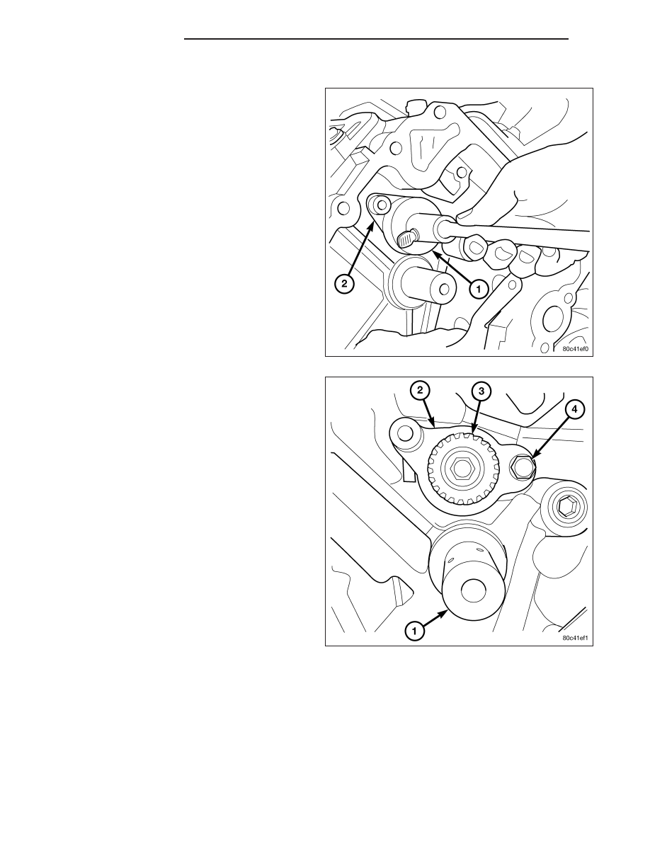
2. Using Special Tool 8641 Counterbalance shaft

remover/installer tool (1), carefully install counter-
balance shaft into engine.

3. Install Counterbalance shaft thrust plate retaining

bolt (4) finger tight.Do not tighten bolt at this time.

4. Position the right side of the thrust plate with the

right chain guide bolt, install bolt finger tight.

5. Torque the thrust plate retaining bolt (4) to 28 N·m

(250 in. lbs.).

6. Remove the chain guide bolt so that guide can be

installed.

9 - 1574

ENGINE - 3.7L

KJ

COVER-TIMING

REMOVAL

1. Disconnect the battery negative cable.

2. Drain cooling system (Refer to 7 - COOLING -

STANDARD PROCEDURE).

3. Remove electric cooling fan and fan shroud assem-

bly.

4. Remove fan and fan drive assembly (Refer to 7 -

COOLING/ENGINE/FAN

DRIVE

VISCOUS

CLUTCH - REMOVAL).

5. Disconnect both heater hoses at timing cover.

6. Disconnect lower radiator hose at engine.

7. Remove accessory drive belt tensioner assembly

(1).

8. Remove crankshaft damper (Refer to 9 - ENGINE/

ENGINE

BLOCK/VIBRATION

DAMPER

-

REMOVAL).

9. Remove the generator (Refer to 8 - ELECTRICAL/

CHARGING/GENERATOR - REMOVAL).

10. Remove A/C compressor (Refer to 24 - HEATING

& AIR

CONDITIONING/PLUMBING/A/C

COM-

PRESSOR - REMOVAL).

CAUTION: The 3.7L engine uses an anerobic
sealer instead of a gasket to seal the front cover
to the engine block, from the factory. For service,
Mopar

T

Grey Engine RTV sealant must be substi-

tuted.

NOTE: It is not necessary to remove the water
pump for timing cover removal.

11. Remove the bolts holding the timing cover to

engine block..

12. Remove the timing cover.

KJ

ENGINE - 3.7L

9 - 1575

INSTALLATION

CAUTION: Do not use oil based liquids to clean
timing cover or block surfaces. Use only rubbing
alcohol, along with plastic or wooden scrapers.
Use no wire brushes or abrasive wheels or metal
scrapers, or damage to surfaces could result.

1. Clean timing chain cover and block surface using

rubbing alcohol.

CAUTION: The 3.7L uses a special anerobic sealer
instead of a gasket to seal the timing cover to the
engine block, from the factory. For service repairs,
Mopar

T

Grey Engine RTV must be used as a sub-

stitute.

2. Inspect the water passage o-rings for any damage,

and replace as necessary.

3. Apply Mopar

T

Grey Engine RTV sealer (3) to the

front cover following the path below, using a 3 to
4mm thick bead.

4. Install cover. Tighten flange head fasteners in

sequence shown to 58 N·m (43 ft. lbs.).

5. Install crankshaft damper (Refer to 9 - ENGINE/

ENGINE BLOCK/VIBRATION DAMPER - INSTAL-
LATION).

6. Install the A/C compressor (Refer to 24 - HEATING

&

AIR

CONDITIONING/PLUMBING/A/C

COM-

PRESSOR - INSTALLATION).

7. Install the generator (Refer to 8 - ELECTRICAL/

CHARGING/GENERATOR - INSTALLATION).

8. Install accessory drive belt tensioner assembly

(Refer to 7 - COOLING/ACCESSORY DRIVE/BELT
TENSIONERS - INSTALLATION).

9. Install radiator upper and lower hoses.

10. Install both heater hoses.

11. Install electric fan shroud and viscous fan drive

assembly (Refer to 7 - COOLING/ENGINE/FAN
DRIVE VISCOUS CLUTCH - INSTALLATION).

12. Fill cooling system (Refer to 7 - COOLING - STANDARD PROCEDURE).

13. Connect the battery negative cable.

9 - 1576

ENGINE - 3.7L

KJ

SHAFT-IDLER

REMOVAL

1. Remove the primary and secondary timing chains and sprockets. Refer to procedure in this section.

NOTE: To remove the idler shaft, it is necessary to tap threads into the shaft, to install the removal tool.

2. Using a 12 mm X 1.75 tap, cut threads in the idler shaft center bore.

3. Cover the radiator core with a suitable cover.

CAUTION: Use care when removing the idler shaft, Do not strike the radiator cooling fins with the slide
hammer.

4. Using Special Tool 8517 Slide Hammer, remove the idler shaft.

INSTALLATION

1. Thoroughly clean the idler shaft bore.

2. Position the idler shaft in the bore.

NOTE: The two lubrication holes in the idler shaft do not require any special alignment.

NOTE: Before using the retaining bolt to install the idler shaft, coat the threads and the pilot on the idler
shaft, with clean engine oil.

3. Using the primary idler sprocket retaining bolt and washer, carefully draw the idler shaft into the bore until fully

seated.

4. Coat the idler shaft with clean engine oil.

5. Install the timing chains and sprockets. Refer to procedure in this section.

KJ

ENGINE - 3.7L

9 - 1577


Content   ..  902  903  904  905   ..