Jeep Liberty KJ. Manual - part 459
POWER OUTLET
DESCRIPTION
One power outlet is installed in the vehicle. It is located in the right rear quarter trim panel. The power outlet base
is secured by a snap fit within the trim panel. A plastic protective cap snaps into the power outlet base when the
power outlet is not being used, and hangs from the power outlet base mount by an integral bail strap while the
power outlet is in use.
The power outlet receptacle unit and the accessory power outlet protective cap are available for service. The power
outlet receptacle cannot be repaired and, if faulty or damaged, it must be replaced.
OPERATION
The power outlet base or receptacle shell is connected to ground, and an insulated contact in the bottom of the
shell is connected to battery current. The power outlet receives battery voltage from a fuse in the Junction Block at
all times.
While the power outlet is very similar to a cigar lighter base unit, it does not include the two small spring-clip retain-
ers inside the bottom of the receptacle shell that are used to secure the cigar lighter heating element to the insu-
lated contact.
DIAGNOSIS AND TESTING - POWER OUTLET
For complete circuit diagrams, refer to Power Outlet in Wiring Diagrams.
1. Check the fused B(+) fuse in the junction block. If OK, go to Step 2. If not OK, repair the shorted circuit or
component as required and replace the faulty fuse.
2. Check for battery voltage at the fused B(+) fuse in the junction block. If OK, go to Step 3. If not OK, repair the
open fused B(+) circuit to the battery as required.
3. Remove the plastic protective cap from the power outlet receptacle. Check for continuity between the inside cir-
cumference of the power outlet receptacle and a good ground. There should be continuity. If OK, go to Step 4.
If not OK, go to Step 5.
4. Check for battery voltage at the insulated contact located at the back of the power outlet receptacle. If not OK,
go to Step 5.
5. Disconnect and isolate the battery negative cable. Remove the power outlet receptacle from the instrument
panel. Disconnect the wire harness connector from the power outlet receptacle. Check for continuity between the
ground circuit cavity of the power outlet wire harness connector and a good ground. There should be continuity.
If OK, go to Step 6. If not OK, repair the open ground circuit to ground as required.
6. Connect the battery negative cable. Check for battery voltage at the fused B(+) circuit cavity of the power outlet
wire harness connector. If OK, replace the faulty power outlet receptacle. If not OK, repair the open fused B(+)
circuit to the junction block fuse as required.
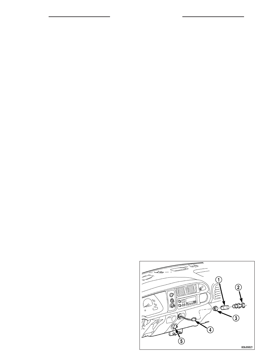
REMOVAL
1. Disconnect and isolate the battery negative cable.
2. Pull the cigar lighter knob and element (2) out of
the cigar lighter receptacle base (1), or unsnap the
protective cap from the power outlet receptacle
base (5).
3. Look inside the cigar lighter or power outlet recep-
tacle base and note the position of the rectangular
retaining bosses of the mount that secures the
receptacle base to the instrument panel.
8W - 97 - 16
8W-97 POWER DISTRIBUTION
KJ