Jeep Grand Cherokee WK. Manual - part 169
C122C-ACTIVE BRAKE BOOSTER CONTROL CIRCUIT SUPPLY VOLTAGE (CONTINUED)
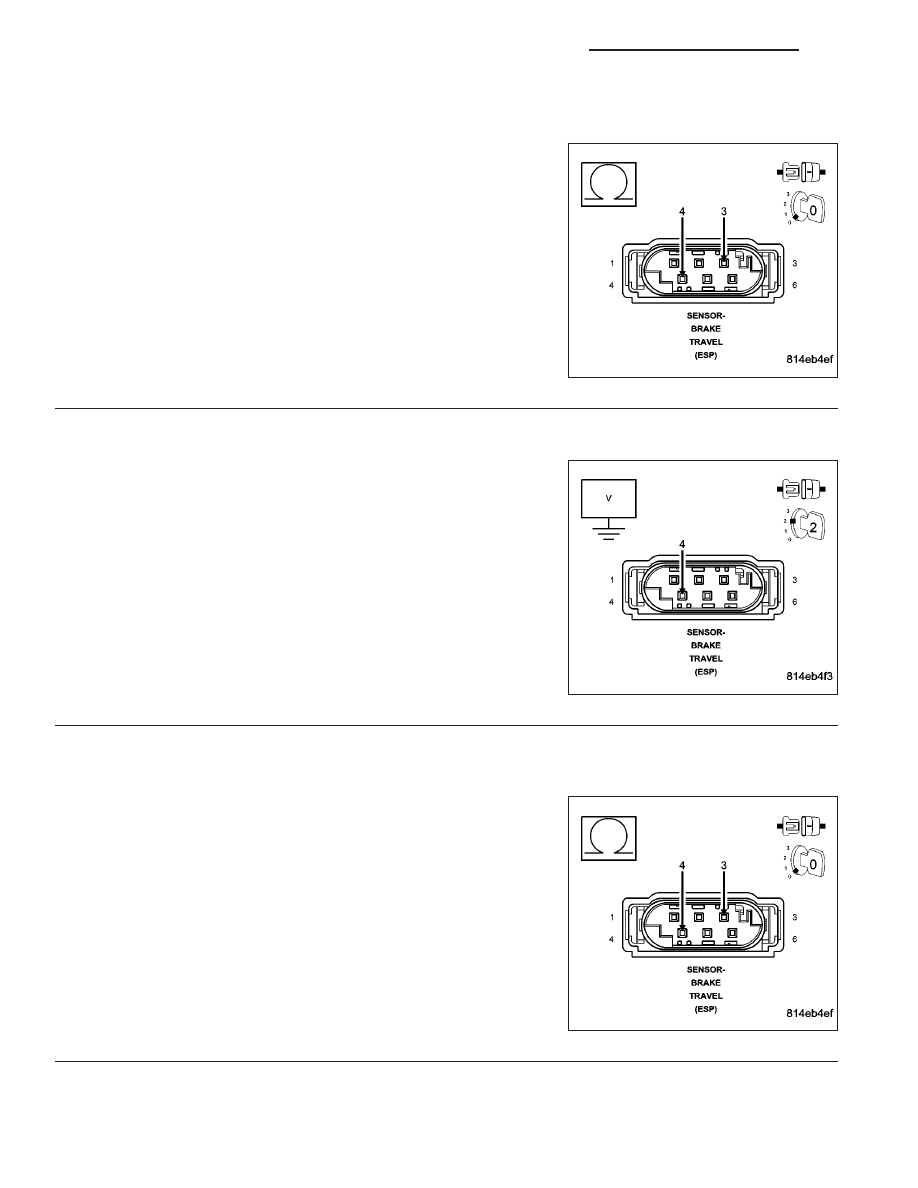
3.
CHECK THE RESISTANCE OF THE ACTIVE BRAKE BOOSTER SOLENOID
Turn the ignition off.
Disconnect the Brake Travel Sensor harness connector.
Measure the resistance between the (B131) Active Brake Booster
Solenoid (+) circuit and the (B984) Brake Pressure Sensor Return cir-
cuit terminals of the Brake Travel Sensor.
Is the resistance between 1 to 2 ohms?
Yes
>> Go To 4
No
>> Replace the Brake Travel Sensor in accordance with the
Service information.
Perform ABS VERIFICATION TEST - VER 1.
4.
CHECK THE VOLTAGE ON THE (B131) ACTIVE BRAKE BOOSTER SOLENOID (+) CIRCUIT
Turn the ignition on.
Measure the voltage of the (B131) Active Brake Booster Solenoid (+)
circuit in the Brake Travel Sensor harness connector.
Is the voltage above 10 volts?
Yes
>> Go To 9
No
>> Go To 5
5.
CHECK FOR A SHORT BETWEEN THE (B131) ACTIVE BRAKE BOOSTER SOLENOID (+) AND (B984)
BRAKE PRESSURE SENSOR RETURN CIRCUITS
Turn the ignition off.
Disconnect the Anti-Lock Brake Module harness connector.
Measure the resistance between the (B131) Active Brake Booster
Solenoid (+) circuit and the (B984) Brake Pressure Sensor Return cir-
cuit.
Is the resistance below 150 ohms?
Yes
>> Repair the (B131) Active Brake Booster Solenoid (+) cir-
cuit for a short to the (B984) Brake Pressure Sensor
Return circuit.
Perform ABS VERIFICATION TEST - VER 1.
No
>> Go To 6
5 - 302
BRAKES - BRAKE CONTROLLER ELECTRICAL DIAGNOSTICS
WK