Jeep Grand Cherokee WK. Manual - part 1626


  Index      Jeep     Jeep Grand Cherokee WK - service repair manual 2005 year


Search            


Content   ..  1624  1625  1626  1627   ..


Jeep Grand Cherokee WK. Manual - part 1626


SEAT BACK-REAR

REMOVAL

1. Remove the rear seat cushion (Refer to 23 -

BODY/SEATS/SEAT CUSHION - REMOVAL).

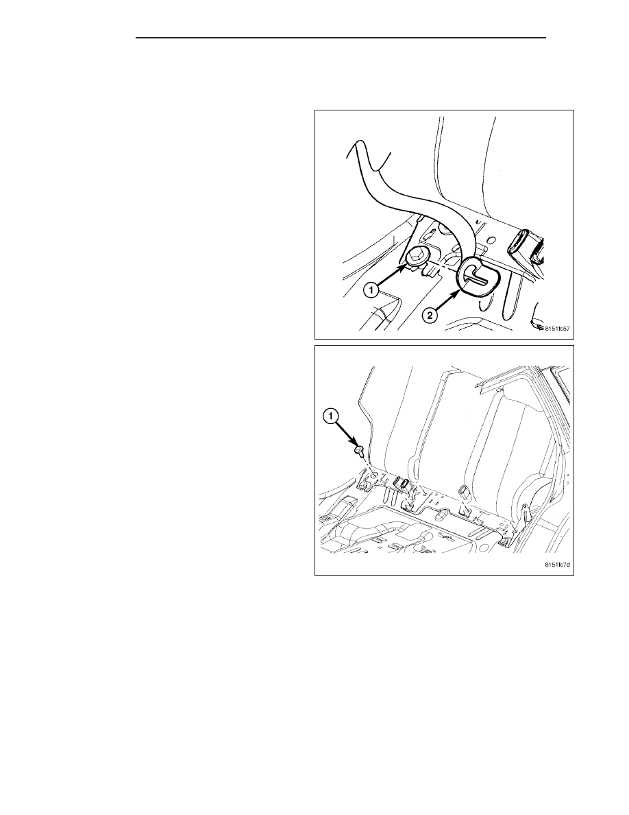
2. Loosen outboard lower anchor bolts (1) and slide

the rear seat belt anchor (2) off the bolt.

3. Remove the four rear seat back mounting bolts (1)

and remove seat back from vehicle.

23 - 162

SEATS

WK

INSTALLATION

1. Place the rear seat back into position by slipping

the hinge bracket onto the two outboard lower
bolts.

2. Install the other four mounting bolts (1). Remember

to install the three inner seat belt buckles. Torque
the bolts to 50 N·m (37 ft. lbs.).

3. Slide the two outboard seat belt anchors (2) onto

the outboard lower bolts (1). Tighten bolts to 50
N·m (37 ft. lbs.).

4. Install the rear seat cushion (Refer to 23 - BODY/

SEATS/SEAT CUSHION - INSTALLATION).

WK

SEATS

23 - 163

SEAT-FRONT

REMOVAL

1. Before proceeding with the following repair proce-

dure, review all warnings and cautions. (Refer to
23 - BODY/SEATS - WARNING)

WARNING: The Seat Weight Sensor is a sensitive,
calibrated unit and must be handled carefully. Do
not drop or handle roughly. If dropped or dam-
aged, replace with another sensor. Failure to fol-
low these instructions may result in personal
injury or death.

WARNING: The front passenger seat must be han-
dled carefully as well. When removing the seat, be
careful when setting on floor not to drop. If
dropped, the sensor may be inoperative. Failure to
follow these instructions may result in personal
injury or death.

WARNING: When the seat is on the floor, no one
should sit in the front passenger seat. This uneven force may damage the sensing ability of the seat weight
sensors. If sat on and damaged, the sensor may be inoperative. Failure to follow these instructions may
result in personal injury or death.

2. Move the seat forward to gain access to the rear bolts.

3. Disconnect and isolate battery negative cable.

4. Remove the cover and lower seat belt anchor (1).

5. Remove the two front (4) and three rear (2) bolts.

6. Disconnect the electrical connectors (3), if equipped, and remove the seat from the vehicle.

INSTALLATION

1. Before proceeding with the following repair proce-

dure, review all warnings and cautions. (Refer to
23 - BODY/SEATS - WARNING)

WARNING: The Seat Weight Sensor is a sensitive,
calibrated unit and must be handled carefully. Do
not drop or handle roughly. If dropped or dam-
aged, replace with another sensor. Failure to fol-
low these instructions may result in personal
injury or death.

WARNING: The front passenger seat must be han-
dled carefully as well. When removing the seat, be
careful when setting on floor not to drop. If
dropped, the sensor may be inoperative. Failure to
follow these instructions may result in personal
injury or death.

23 - 164

SEATS

WK

WARNING: When the seat is on the floor, no one should sit in the front passenger seat. This uneven force
may damage the sensing ability of the seat weight sensors. If sat on and damaged, the sensor may be
inoperative. Failure to follow these instructions may result in personal injury or death.

2. Position the seat into the vehicle and connect the electrical connectors (3), if equipped.

3. Install the two front bolts (4) and three rear bolts (2).

4. Tighten the front inner bolt to 27 N·m (20 ft. lbs.) then tighten the front outer bolt to 27 N·m (20 ft. lbs.).

5. Tighten the rear bolts to 47 N·m (35 ft. lbs.).

6. Install the lower seat belt anchor (1) and install the bolt.

7. Tighten the bolt to 39 N·m (29 ft. lbs.) and install the trim cover (1).

8. Do not reconnect the battery negative cable at this time. The supplemental restraint system verification test pro-

cedure should be performed following service of any supplemental restraint system component. (Refer to 8 -
ELECTRICAL/RESTRAINTS - STANDARD PROCEDURE - VERIFICATION TEST).

9. Following successful completion of the supplemental restraint system verification test procedure, perform the

Occupant Classification System Verification Test using a scan tool. (Refer to 8 - ELECTRICAL/RESTRAINTS -
*OCS VERIFICATION TEST - VER 1)

SUPPORT-LUMBAR

REMOVAL

1. Before proceeding with the following repair proce-

dure, review all warnings and cautions. (Refer to
23 - BODY/SEATS - WARNING)

2. Remove the seat back cushion/cover. (Refer to 23

- BODY/SEATS/SEAT BACK CUSHION / COVER -
FRONT - REMOVAL)

3. Release the lumbar mat side wires (1) by pulling

out on the wire supports and then pulling them in.

WK

SEATS

23 - 165


Content   ..  1624  1625  1626  1627   ..