Jeep Grand Cherokee WK. Manual - part 1374


  Index      Jeep     Jeep Grand Cherokee WK - service repair manual 2005 year


Search            


Content   ..  1372  1373  1374  1375   ..


Jeep Grand Cherokee WK. Manual - part 1374


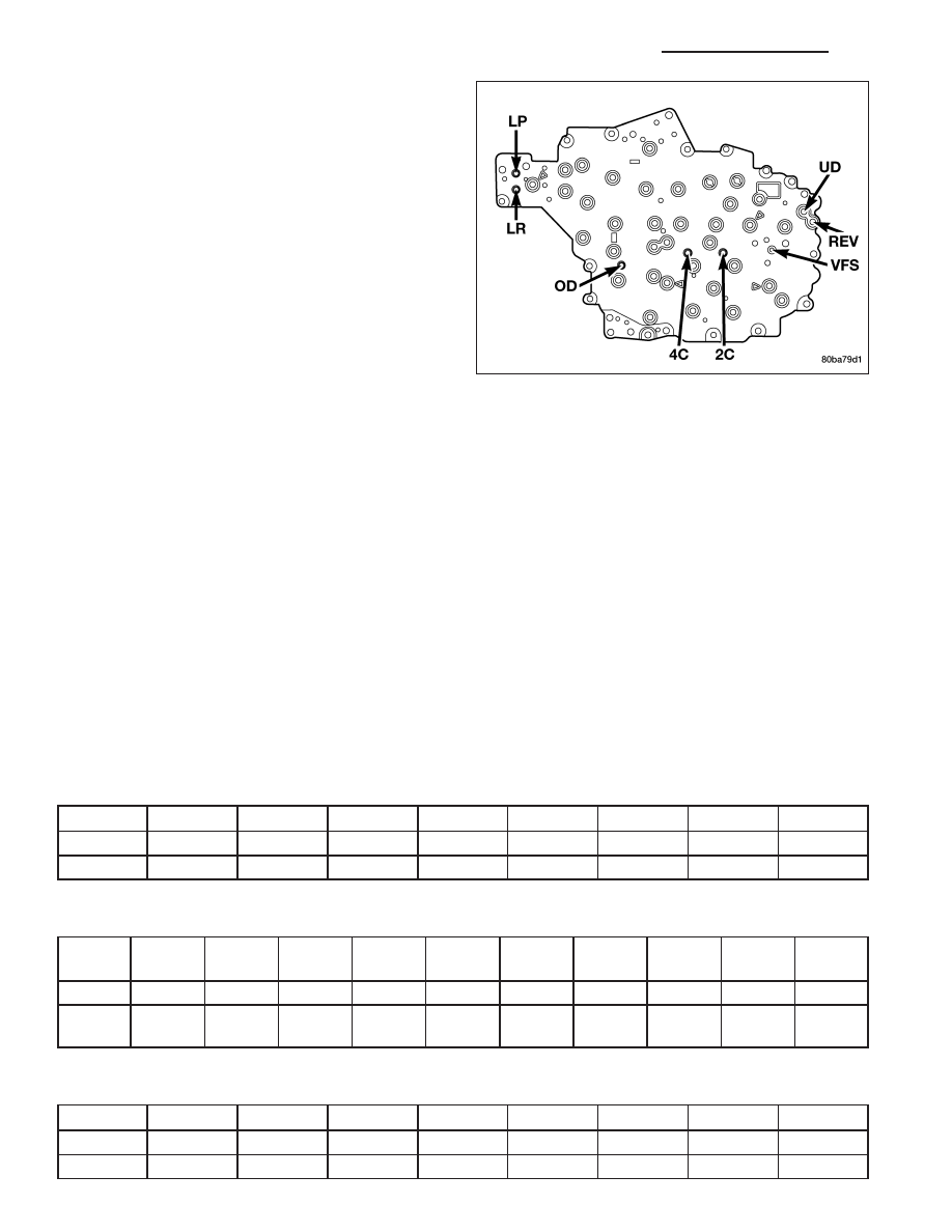
Refer to the Pressure Tap Locations graphic for cor-
rect pressure tap location identification.

TEST PROCEDURE

All pressure readings should be taken with the transmission fluid level full, transmission oil at the normal operating
temperature, and the engine at 1500 rpm. Check the transmission for proper operation in each gear position that is
in question or if a specific element is in question, check the pressure readings in at least two gear positions that
employ that element. Refer to the Hydraulic Schematics at the rear of this section to determine the correct pres-
sures for each element in a given gear position.

NOTE: The 45RFE/545RFE utilizes closed loop control of pump line pressure. The pressure readings may
therefore vary greatly but should always follow line pressure.

Some common pressures that can be measured to evaluate pump and clutch performance are the upshift/downshift
pressures, garage shift pressures, and TCC pressure. The upshift/downshift pressure for all shifts are shown in
UPSHIFT PRESSURES and DOWNSHIFT PRESSURES . In-gear maximum pressure for each gear position is
shown in IN-GEAR PRESSURES . The garage shift pressure when performing a N-R shift is 220 psi for 3.7L/4.7L
equipped vehicles and 250 psi for 5.7L equipped vehicles. The garage shift pressure for the R-N shift is 120 psi.
The garage shift pressure for the N-1 shift is 135 psi for 3.7L/4.7L equipped vehicles and 165 psi for 5.7L equipped
vehicles. Torque converter lock-up pressure is 120 psi for 3.7L/4.7L equipped vehicles and 125 psi for 5.7L
equipped vehicles.

UPSHIFT PRESSURES

ENGINE

1-2

2-3

2prime-3

3-4

2prime-4

2-5

3-5

4-5

5.7L

150

125

125

135

135

135

135

135

3.7L/4.7L

120

120

120

120

120

120

120

130

DOWNSHIFT PRESSURES

ENGINE

5-4

5-3

5-2

4-3

4-
2prime

3-2

3-
2prime

2prime-1 2-1

3-1

5.7L

135

135

135

135

135

135

135

135

135

135

3.7L/
4.7L

120

120

120

120

120

120

120

120

120

120

IN-GEAR PRESSURES

ENGINE

1

2

2prime

3

4

5

NEUTRAL

REVERSE

5.7L

160

135

135

135

135

135

120

250

3.7L/4.7L

135

120

120

120

120

120

120

220

21 - 306

AUTOMATIC TRANSMISSION - 545RFE - SERVICE INFORMATION

WK

AIR CHECKING TRANSMISSION CLUTCH OPERATION

Air-pressure testing can be used to check transmis-
sion clutch operation. The test can be conducted with
the transmission either in the vehicle or on the work
bench, as a final check.

Air-pressure testing requires that the oil pan and valve
body be removed from the transmission. The clutch
apply passages are shown in the Air Pressure Test
Passages graphic.

NOTE: The air supply which is used must be free
of moisture and dirt. Use a pressure of 30 psi to
test clutch operation.

Apply air pressure at each port. If the clutch is func-
tioning, a soft thump will be heard as the clutch is
applied. The clutch application can also be felt by
touching the appropriate element while applying air
pressure. As the air pressure is released, the clutch
should also release.

CONVERTER HOUSING FLUID LEAK

When diagnosing converter housing fluid leaks, two items must be established before repair.

1. Verify that a leak condition actually exists.

2. Determined the true source of the leak.

Some suspected converter housing fluid leaks may not be leaks at all. They may only be the result of residual fluid
in the converter housing, or excess fluid spilled during factory fill or fill after repair. Converter housing leaks have
several potential sources. Through careful observation, a leak source can be identified before removing the trans-
mission for repair. Torque converter seal leaks tend to move along the drive hub and onto the rear of the converter.
Pump cover seal leaks tend to run down the cover and the inside surface of the bellhousing.

Some leaks, or suspected leaks, may be particularly difficult to locate. If necessary, a Mopar

T

approved dye should

be used to locate and confirm a leak.

1 - LOW REVERSE CLUTCH
2 - 4TH CLUTCH
3 - 2ND CLUTCH
4 - OVERDRIVE CLUTCH
5 - UNDERDRIVE CLUTCH
6 - REVERSE CLUTCH

WK

AUTOMATIC TRANSMISSION - 545RFE - SERVICE INFORMATION

21 - 307

TORQUE CONVERTER LEAK POINTS

Possible sources of converter leaks are:

1. Leaks at the weld joint around the outside diameter

weld.

2. Leaks at the converter hub weld.

In most cases, a torque converter which is wet from
transmission fluid indicates a leak at one of these
areas.

STANDARD PROCEDURE - ALUMINUM THREAD REPAIR

Damaged or worn threads in the aluminum transmission case and valve body can be repaired by the use of Heli-
Coils™, or equivalent. This repair consists of drilling out the worn-out damaged threads. Then tap the hole with a
special Heli-Coil™ tap, or equivalent, and installing a Heli-Coil™ insert, or equivalent, into the hole. This brings the
hole back to its original thread size.

Heli-Coil™, or equivalent, tools and inserts are readily available from most automotive parts suppliers.

REMOVAL

CAUTION: The transmission and torque converter must be removed as an assembly to avoid component
damage. The converter driveplate, oil pump, or oil seal can be damaged if the converter is left attached to
the driveplate during removal. Be sure to remove the transmission and converter as an assembly.

1 - TURBINE ASSEMBLY
2 - STATOR
3 - CONVERTER HUB
4 - O-RING
5 - IMPELLER ASSEMBLY
6 - CONVERTER CLUTCH PISTON
7 - TURBINE HUB

21 - 308

AUTOMATIC TRANSMISSION - 545RFE - SERVICE INFORMATION

WK

1. Disconnect the negative battery cable.

2. Raise and support the vehicle

3. Remove the rear propeller shaft. (Refer to 3 - DIF-

FERENTIAL & DRIVELINE/PROPELLER SHAFT/
PROPELLER SHAFT - REMOVAL)

4. Remove the front propeller shaft. (Refer to 3 - DIF-

FERENTIAL & DRIVELINE/PROPELLER SHAFT/
PROPELLER SHAFT - REMOVAL)

5. Remove the engine to transmission structural cover

(1), 5.7L shown. (Refer to 9 - ENGINE/ENGINE
BLOCK/STRUCTURAL COVER - REMOVAL)

6. Remove the torque converter bolts (3).

WK

AUTOMATIC TRANSMISSION - 545RFE - SERVICE INFORMATION

21 - 309


Content   ..  1372  1373  1374  1375   ..