Jeep Grand Cherokee WK. Manual - part 1028


  Index      Jeep     Jeep Grand Cherokee WK - service repair manual 2005 year


Search            


Content   ..  1026  1027  1028  1029   ..


Jeep Grand Cherokee WK. Manual - part 1028


P0622-GENERATOR FIELD CONTROL CIRCUIT (CONTINUED)

5.

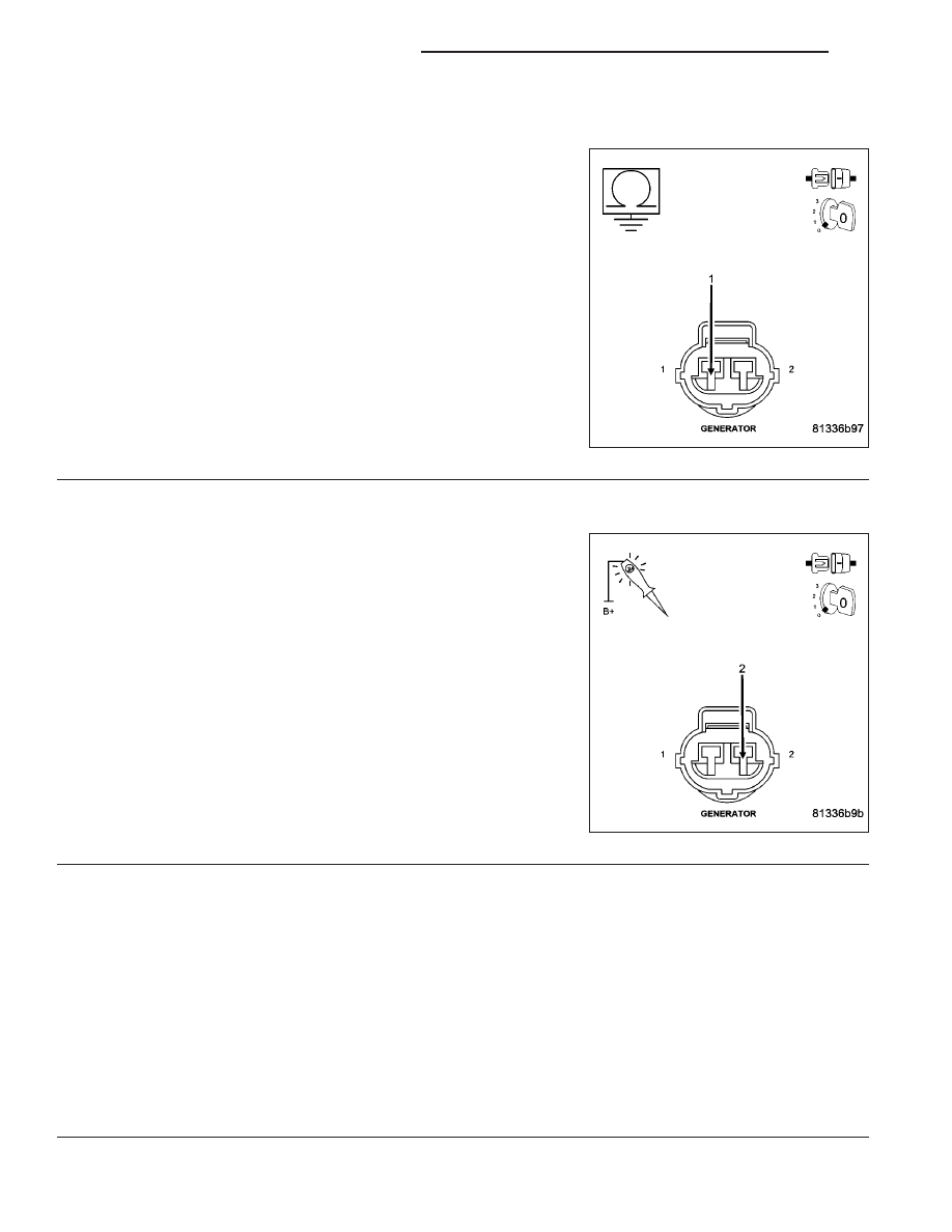
(K125) GEN FIELD CIRCUIT SHORTED TO GROUND

Measure the resistance between ground and the (K125) Gen Field
Control circuit in the Generator Field harness connector.

Is the resistance below 100 ohms?

Yes

>> Repair the short to ground in the (K125) Gen Field Control

circuit.

Perform the POWERTRAIN VERIFICATION TEST. (Refer
to 9 - ENGINE - STANDARD PROCEDURE)

No

>> Go To 6

6.

(Z385) GROUND CIRCUIT OPEN

Using a 12-volt test light connected to battery voltage, probe the
(Z385) Ground circuit in the Gen Field harness connector.

Does the test light illuminate brightly?

Yes

>> Go To 7

No

>> Repair the open in the (Z385) Ground circuit.

Perform the POWERTRAIN VERIFICATION TEST. (Refer
to 9 - ENGINE - STANDARD PROCEDURE)

7.

PCM

NOTE: Before continuing, check the PCM harness connector terminals for corrosion, damage, or terminal
push out. Repair as necessary.
Using the schematics as a guide, inspect the wire harness and connectors. Pay particular attention to all Power and
Ground circuits.

Were there any problems found?

Yes

>> Repair as necessary.

Perform the POWERTRAIN VERIFICATION TEST. (Refer to 9 - ENGINE - STANDARD PROCEDURE)

No

>> Replace and program the Powertrain Control Module per Service Information.

Perform the POWERTRAIN VERIFICATION TEST. (Refer to 9 - ENGINE - STANDARD PROCEDURE)

9 - 708

ENGINE ELECTRICAL DIAGNOSTICS

WK

P0627-FUEL PUMP RELAY CIRCUIT

WK

ENGINE ELECTRICAL DIAGNOSTICS

9 - 709

P0627-FUEL PUMP RELAY CIRCUIT (CONTINUED)

For the Engine circuit diagram (Refer to 9 - ENGINE - SCHEMATICS AND DIAGRAMS).

For a complete wiring diagram Refer to Section 8W.

When Monitored:
With the ignition on. Battery voltage greater than 10.4 volts and the ASD sense switch is on.

Set Condition:
Actual Fuel Pump Relay state is not equal to desired state. One Trip Fault. Three good trips to turn off the MIL.

Possible Causes

(A916) FUSED B+ CIRCUIT

(F942) FUSED IGNITION SWITCH OUTPUT CIRCUIT

(K31) FUEL PUMP RELAY CONTROL CIRCUIT

(K31) FUEL PUMP RELAY CONTROL CIRCUIT SHORTED TO GROUND

FUEL PUMP RELAY

PCM

Always perform the Pre-Diagnostic Troubleshooting procedure before proceeding. (Refer to 9 - ENGINE -
DIAGNOSIS AND TESTING).

Diagnostic Test

1.

FUEL PUMP RELAY OPERATION

Ignition on, engine not running.

With a scan tool, actuate the Fuel Pump Relay.

Is the Fuel Pump Relay operating?

Yes

>> Refer to the INTERMITTENT CONDITION Diagnostic Procedure.

Perform the POWERTRAIN VERIFICATION TEST. (Refer to 9 - ENGINE - STANDARD PROCEDURE)

No

>> Go To 2

2.

FUEL PUMP RELAY

Turn the ignition off.

Remove the Fuel Pump Relay from the IPM.

Measure the resistance of the Fuel Pump Relay Coil.

Is the resistance between 70 to 90 ohms?

Yes

>> Go To 3

No

>> Replace the Fuel Pump Relay.

Perform the POWERTRAIN VERIFICATION TEST. (Refer to 9 - ENGINE - STANDARD PROCEDURE)

9 - 710

ENGINE ELECTRICAL DIAGNOSTICS

WK

P0627-FUEL PUMP RELAY CIRCUIT (CONTINUED)

3.

(A916) FUSED B+ CIRCUIT

Ignition on, engine not running.

Using a 12-volt test light connected to ground, probe the (A916) Fused B+ circuit.

Does the test light illuminate brightly?

Yes

>> Go To 4

No

>> Repair the open or short to ground in the (A916) Fused B+ circuit. Inspect the related fuse and repair

as necessary.

Perform the POWERTRAIN VERIFICATION TEST. (Refer to 9 - ENGINE - STANDARD PROCEDURE)

4.

(F942) FUSED IGNITION SWITCH OUTPUT CIRCUIT

Ignition on, engine not running.

Using a 12-volt test light connected to ground, probe the (F942) Fused Ignition Switch Output circuit.

Does the test light illuminate brightly?

Yes

>> Go To 5

No

>> Repair the open or short to ground in the (F942) Fused Ignition Switch Output circuit. Inspect the related

fuse and repair as necessary.

Perform the POWERTRAIN VERIFICATION TEST. (Refer to 9 - ENGINE - STANDARD PROCEDURE)

5.

(K31) CONTROL CIRCUIT OPEN

Turn the ignition off.

Disconnect the C3 PCM harness connector.

CAUTION: Do not probe the PCM harness connectors. Probing the PCM harness connectors will damage
the PCM terminals resulting in poor terminal to pin connection. Install Miller Special Tool #8815 to perform
diagnosis.
Measure the resistance of the (K31) Fuel Pump Relay Control circuit from the IPM to the appropriate terminal of
special tool #8815.

Is the resistance below 5.0 ohms?

Yes

>> Go To 6

No

>> Repair the open in the (K31) Fuel Pump Relay Control circuit.

Perform the POWERTRAIN VERIFICATION TEST. (Refer to 9 - ENGINE - STANDARD PROCEDURE)

6.

(K31) CONTROL CIRCUIT SHORTED TO GROUND

Measure the resistance between ground and the (K31) Fuel Pump Relay Control circuit in the IPM.

Is the resistance below 100 ohms?

Yes

>> Repair the short to ground in the (K31) Fuel Pump Relay Control circuit.

Perform the POWERTRAIN VERIFICATION TEST. (Refer to 9 - ENGINE - STANDARD PROCEDURE)

No

>> Go To 7

WK

ENGINE ELECTRICAL DIAGNOSTICS

9 - 711


Content   ..  1026  1027  1028  1029   ..