Jeep Grand Cherokee WJ. Manual - part 122


  Index      Jeep     Jeep Grand Cherokee WJ - service repair manual 2001 year


Search            


Content   ..  120  121  122  123   ..


Jeep Grand Cherokee WJ. Manual - part 122


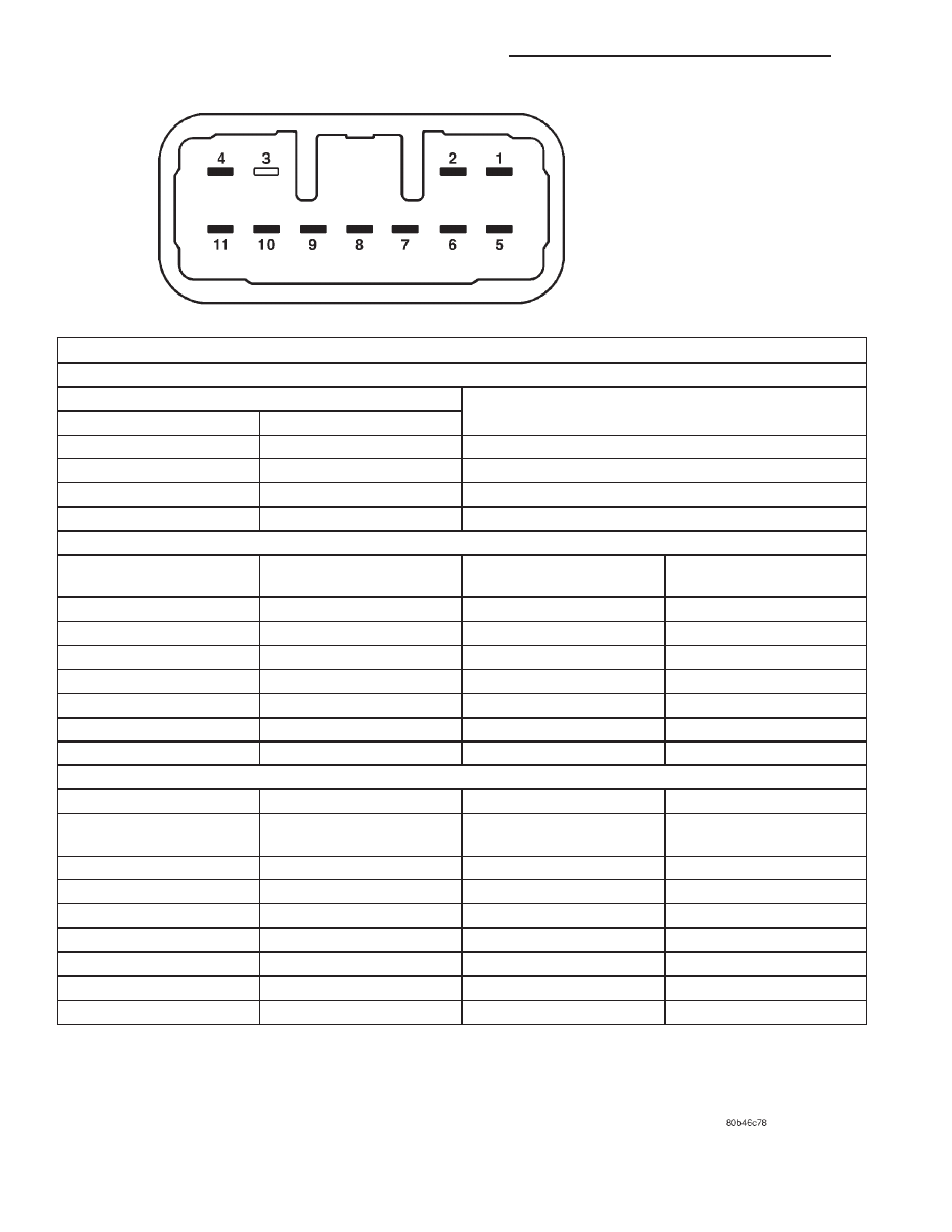
LEFT (LIGHTING) MULTI-FUNCTION SWITCH

TURN SIGNAL AND HAZARD WARNING SWITCH TESTS

SWITCH POSITION

CONTINUITY BETWEEN

TURN

HAZARD

Neutral

Off

No Related Continuity

Left

Off

Pins 2 & 8

Right

Off

Pins 2 & 7

Neutral

On

Pins 2 & 9

EXTERIOR LIGHTING SWITCH TESTS

SWITCH POSITION

CONTINUITY BETWEEN

RESISTANCE BETWEEN

RESISTANCE RANGE

(OHMS)

Off

Pins 4 & 11

3743 - 3824

Park Lamps On

Pins 4 & 11

901 - 926

Head Lamps On

Pins 4 & 11

345 - 358

Auto Headlamps On

Pins 4 & 11

74 - 81

Fog Lamps

Pins 1 & 2

Optical Horn

Pins 2 & 5

High Beam

Pins 2 & 6

INTERIOR LIGHTING SWITCH TESETS

Dome Lamp Disable On

Pins 4 & 9

63 - 70

Panel Lamps Dimming

Position 1

Pins 4 & 9

198 - 208

Dimming Position 2

Pins 4 & 9

551 - 569

Dimming Position 3

Pins 4 & 9

905 - 929

Dimming Position 4

Pins 4 & 9

1258 - 1290

Dimming Position 5

Pins 4 & 9

1611 - 1651

Dimming Position 6

Pins 4 & 9

1965 - 2011

Parade Mode On

Pins 4 & 9

3534 - 3611

Dome Lamp Enable On

Pins 4 & 9

7811 - 7974

Fig. 3 Left Multi-Function Switch Test

8J - 8

TURN SIGNAL AND HAZARD WARNING SYSTEMS

WJ

DIAGNOSIS AND TESTING (Continued)

REMOVAL AND INSTALLATION

COMBINATION FLASHER

WARNING: ON VEHICLES EQUIPPED WITH AIR-
BAGS, REFER TO GROUP 8M - PASSIVE RESTRAINT
SYSTEMS BEFORE ATTEMPTING ANY STEERING
WHEEL,

STEERING

COLUMN,

OR

INSTRUMENT

PANEL COMPONENT DIAGNOSIS OR SERVICE. FAIL-
URE TO TAKE THE PROPER PRECAUTIONS COULD
RESULT IN ACCIDENTAL AIRBAG DEPLOYMENT
AND POSSIBLE PERSONAL INJURY.

REMOVAL

(1) Disconnect and isolate the battery negative

cable.

(2) Remove the steering column opening cover

from the instrument panel. Refer to Steering Col-
umn Opening Cover 
in the Removal and Installa-
tion section of Group 8E - Instrument Panel Systems
for the procedures.

(3) Remove the combination flasher from the junc-

tion block (Fig. 4).

INSTALLATION

(1) Position the combination flasher in the proper

receptacle in the junction block.

(2) Align the combination flasher terminals with

the terminal cavities in the junction block receptacle.

(3) Push in firmly on the combination flasher until

the terminals are fully seated in the terminal cavities
in the junction block receptacle.

(4) Install the steering column opening cover onto

the instrument panel. Refer to Steering Column
Opening Cover 
in the Removal and Installation sec-
tion of Group 8E - Instrument Panel Systems for the
procedures.

(5) Reconnect the battery negative cable.

TURN SIGNAL AND HAZARD WARNING
SWITCH

WARNING: ON VEHICLES EQUIPPED WITH AIR-
BAGS, REFER TO GROUP 8M - PASSIVE RESTRAINT
SYSTEMS BEFORE ATTEMPTING ANY STEERING
WHEEL,

STEERING

COLUMN,

OR

INSTRUMENT

PANEL COMPONENT DIAGNOSIS OR SERVICE. FAIL-
URE TO TAKE THE PROPER PRECAUTIONS COULD
RESULT IN ACCIDENTAL AIRBAG DEPLOYMENT
AND POSSIBLE PERSONAL INJURY.

REMOVAL

(1) Disconnect and isolate the battery negative

cable.

(2) Remove the screw that secures the lower tilting

steering column shroud to the steering column multi-
function switch mounting housing (Fig. 5).

Fig. 4 Combination Flasher

1 – COMBINATION FLASHER
2 – JUNCTION BLOCK

Fig. 5 Steering Column Shrouds Remove/Install

1 – UPPER TILTING COLUMN SHROUD
2 – FIXED COLUMN SHROUD
3 – LOWER TILTING COLUMN SHROUD
4 – SCREW

WJ

TURN SIGNAL AND HAZARD WARNING SYSTEMS

8J - 9

(3) Unsnap the two halves of the tilting steering

column shroud from each other and remove both
halves from the steering column.

(4) Disconnect the instrument panel wire harness

connector from the turn signal and hazard warning
(left multi-function) switch connector receptacle.

(5) Remove the two screws that secure the left

multi-function switch to the multi-function switch
mounting housing (Fig. 6).

(6) Remove the left multi-function switch from the

multi-function switch mounting housing.

INSTALLATION

(1) Position the left multi-function switch onto the

multi-function switch mounting housing.

(2) Install and tighten the two screws that secure

the left multi-function switch to the multi-function
switch mounting housing. Tighten the screws to 2.5
N·m (22 in. lbs.).

(3) Reconnect the instrument panel wire harness

connector to the left multi-function switch connector
receptacle.

(4) Position the lower tilting steering column

shroud to the underside of the steering column.

(5) Install and tighten the screw that secures the

lower tilting steering column shroud to the multi-
function switch mounting housing. Tighten the screw
to 1.9 N·m (17 in. lbs.).

(6) Position the upper tilting column shroud over

the steering column with the hazard warning switch
button inserted through the hole in the upper surface
of the shroud. Align the upper tilting steering column
shroud to the lower shroud and snap the two shroud
halves together.

(7) Reconnect the battery negative cable.

TURN SIGNAL CANCELLING CAM

WARNING: ON VEHICLES EQUIPPED WITH AIR-
BAGS, REFER TO GROUP 8M - PASSIVE RESTRAINT
SYSTEMS BEFORE ATTEMPTING ANY STEERING
WHEEL,

STEERING

COLUMN,

OR

INSTRUMENT

PANEL COMPONENT DIAGNOSIS OR SERVICE. FAIL-
URE TO TAKE THE PROPER PRECAUTIONS COULD
RESULT IN ACCIDENTAL AIRBAG DEPLOYMENT
AND POSSIBLE PERSONAL INJURY.

REMOVAL

NOTE: Before starting this procedure, be certain to
turn the steering wheel until the front wheels are in
the straight-ahead position.

(1) Place the front wheels in the straight-ahead

position.

(2) Remove the driver side airbag module from the

steering wheel. Refer to Driver Side Airbag Mod-
ule 
in the Removal and Installation section of Group
8M - Passive Restraint Systems for the procedures.

(3) Disconnect the steering wheel wire harness

connector from the upper clockspring connector
receptacle, which is located between the two upper
spokes of the armature within the hub cavity of the
steering wheel.

(4) Remove the nut that secures the steering wheel

armature to the steering column upper shaft, which
is located within the hub cavity of the steering wheel.

(5) Pull the steering wheel off of the steering col-

umn upper shaft spline using a two-jawed puller
(Special Tool C-3894-A) (Fig. 7). When installing the
puller onto the steering wheel, be certain that each
jaw of the puller is seated in the pocket that is cast
into the underside of the steering wheel armature on
each side of the hub (Fig. 8). Also, if the clockspring
is to be reused, be certain not to damage or deform
the clockspring case when positioning the jaws of the
puller below the steering wheel armature hub.

(6) Remove the screw that secures the lower tilting

steering column shroud to the steering column multi-
function switch mounting housing (Fig. 9).

(7) Unsnap the two halves of the tilting steering

column shroud from each other and remove both
halves from the steering column.

(8) Disconnect the instrument panel wire harness

connectors from the lower clockspring connector
receptacles, the right multi-function switch connector
receptacle and the left multi-function switch connec-
tor receptacle.

(9) From the underside of the steering column,

remove the one screw that secures the multi-function
switch mounting housing to the top of the column
housing (Fig. 10).

Fig. 6 Left Multi-Function Switch Remove/Install

1 – SCREW (2)
2 – STEERING COLUMN
3 – MULTI-FUNCTION SWITCH MOUNTING HOUSING
4 – LEFT MULTI-FUNCTION SWITCH

8J - 10

TURN SIGNAL AND HAZARD WARNING SYSTEMS

WJ

REMOVAL AND INSTALLATION (Continued)

Fig. 7 Steering Wheel Remove/Install

1 – PULLER
2 – STEERING WHEEL

Fig. 8 Steering Wheel Armature Pockets

1 – STEERING WHEEL POCKETS

Fig. 9 Steering Column Shrouds Remove/Install

1 – UPPER TILTING COLUMN SHROUD
2 – FIXED COLUMN SHROUD
3 – LOWER TILTING COLUMN SHROUD
4 – SCREW

Fig. 10 Multi-Function Switch Mounting Housing

Screw Remove/Install

1 – CLOCK SPRING
2 – MOUNTING SCREW
3 – MULTIFUNCTION SWITCH ASSEMBLY

WJ

TURN SIGNAL AND HAZARD WARNING SYSTEMS

8J - 11

REMOVAL AND INSTALLATION (Continued)


Content   ..  120  121  122  123   ..