Jeep Grand Cherokee WJ. Manual - part 62


  Index      Jeep     Jeep Grand Cherokee WJ - service repair manual 2001 year


Search            


Content   ..  60  61  62  63   ..


Jeep Grand Cherokee WJ. Manual - part 62


ACCESSING DIAGNOSTIC TROUBLE CODES

A stored Diagnostic Trouble Code (DTC) can be dis-

played by cycling the ignition key On-Off-On-Off-On
within three seconds and observing the malfunction
indicator lamp. This lamp is displayed on the instru-
ment panel as the CHECK ENGINE lamp (Fig. 17).

They can also be displayed through the use of the

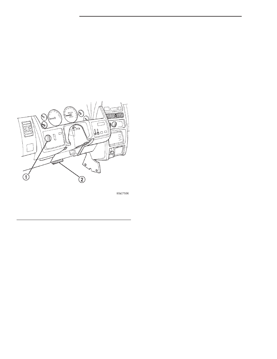
Diagnostic Readout Box (DRB) scan tool. The DRB
connects to the data link connector, left of the steer-
ing column above the brake pedal (Fig. 18). For oper-
ation of the DRB, refer to the appropriate Powertrain
Diagnostic Procedures service manual.

EXAMPLES:
• If the lamp (Fig. 17) flashes 1 time, pauses and

flashes 2 more times, a flashing Diagnostic Trouble
Code (DTC) number 12 is indicated. If this code is
observed, it is indicating that the battery has been
disconnected within the last 50 key-on cycles. It
could also indicate that battery voltage has been dis-
connected to the PCM. In either case, other DTC’s
may have been erased.

• If the lamp flashes 1 time, pauses and flashes 7

more times, a flashing Diagnostic Trouble Code
(DTC) number 17 is indicated.

After

any

stored

DTC

information

has

been

observed, the display will end with a flashing DTC
number 55. This will indicate the end of all stored
information.

ERASING TROUBLE CODES

After the problem has been repaired, use the DRB

scan tool to erase a DTC. Refer to the appropriate

Powertrain Diagnostic Procedures service manual for
operation of the DRB scan tool.

DRB SCAN TOOL

For operation of the DRB scan tool, refer to the

appropriate Powertrain Diagnostic Procedures ser-
vice manual.

WATER PUMP TESTS

LOOSE IMPELLER—4.0L and 4.7L

NOTE: Due to the design of the 4.0L and 4.7L
engine water pumps, testing the pump for a loose
impeller must be done by verifying coolant flow in
the radiator. To accomplish this refer to the follow-
ing procedure.

DO NOT WASTE reusable coolant. If solution is

clean, drain coolant into a clean container for reuse.

(1) Drain coolant until the first row of cores is vis-

ible in the radiator.

(2) Leaving the radiator cap off, start the engine
(3) While looking into the radiator through the

radiator fill neck, raise engine rpm to 2000 RPM.
Observe the flow of coolant from the first row of
cores.

(4) If there is no flow or very little flow visable,

replace the water pump.

INSPECTING FOR INLET RESTRICTIONS

Inadequate heater performance may be caused by

a metal casting restriction in the heater hose inlet.

DO NOT WASTE reusable coolant. If solution is

clean, drain the coolant into a clean container for
reuse.

WARNING: DO

NOT

LOOSEN

THE

RADIATOR

DRAINCOCK WITH THE SYSTEM HOT AND UNDER
PRESSURE. SERIOUS BURNS FROM THE COOL-
ANT CAN OCCUR.

(1) Drain sufficient coolant from the radiator to

decrease the level below the heater hose inlet. On
4.7L engines this requires complete draining.

(2) Remove the heater hose.
(3) Inspect the inlet for metal casting flash or

other restrictions.

NOTE: On 4.0L engines remove the pump from the
engine before removing restriction to prevent con-
tamination of the coolant with debris. Refer to
Water Pump Removal in this section. On 4.7L
engine remove the fitting from the timing chain
cover, If the restriction is in the timing chain cover,
remove the timing chain cover. Refer to Timing
Chain Cover in Group 9 Engine, for procedure.

Fig. 18 Data Link Connector Location

1 – HEADLAMP SWITCH
2 – DATA LINK CONNECTOR (LEFT SIDE OF COLUMN ABOVE

BRAKE PEDAL)

7 - 10

COOLING SYSTEM

WJ

DIAGNOSIS AND TESTING (Continued)

THERMOSTAT

ON-BOARD DIAGNOSTICS

All models are equipped with On-Board Diagnos-

tics for certain cooling system components. Refer to
On-Board Diagnostics (OBD) in the Diagnosis section
of this group for additional information. If the pow-
ertrain control module (PCM) detects low engine cool-
ant temperature, it will record a Diagnostic Trouble
Code (DTC). Refer to the Diagnosis section of this
group for other probable causes. For other DTC num-
bers, refer to On-Board Diagnostics in Group 25,
Emission Control Systems.

The DTC can also be accessed through the DRB

scan tool. Refer to the appropriate Powertrain Diag-
nostic Procedures manual for diagnostic information
and operation of the DRB scan tool.

SERPENTINE DRIVE BELT DIAGNOSIS

When diagnosing serpentine drive belts, small

cracks that run across ribbed surface of belt from rib
to rib (Fig. 19), are considered normal. These are not
a reason to replace belt. However, cracks running
along a rib (not across) are not normal. Any belt
with cracks running along a rib must be replaced
(Fig. 19). Also replace belt if it has excessive wear,
frayed cords or severe glazing.

Refer to the Serpentine Drive Belt Diagnosis

charts for further belt diagnosis.

SERPENTINE DRIVE BELT DIAGNOSIS

CONDITION

POSSIBLE CAUSES

CORRECTION

RIB CHUNKING (ONE OR MORE
RIBS HAS SEPARATED FROM
BELT BODY)

1. Foreign objects imbedded in pulley
grooves.

1. Remove foreign objects from
pulley grooves. Replace belt.

2. Installation damage.

2. Replace belt.

RIB OR BELT WEAR

1. Pulley(s) misaligned.

1. Align pulley(s).

2. Abrasive environment.

2. Clean pulley(s). Replace belt if
necessary.

3. Rusted pulley(s).

3. Clean rust from pulley(s).

4. Sharp or jagged pulley groove tips.

4. Replace pulley.

5. Rubber deteriorated.

5. Replace belt.

LONGITUDINAL BELT
CRACKING (CRACKS BETWEEN
TWO RIBS)

1. Belt has mistracked from pulley
groove.

1. Replace belt.

2. Pulley groove tip has worn away
rubber to tensile member.

2. Replace belt.

Fig. 19 Serpentine Accessory Drive Belt Wear

Patterns

1 – NORMAL CRACKS BELT OK
2 – NOT NORMAL CRACKS REPLACE BELT

WJ

COOLING SYSTEM

7 - 11

DIAGNOSIS AND TESTING (Continued)

SERPENTINE DRIVE BELT DIAGNOSIS

CONDITION

POSSIBLE CAUSES

CORRECTION

BELT SLIPS

1. Belt slipping because of insufficient
tension.

1. Replace automatic belt tensioner.

2. Belt routed

2. Verify belt routing.

incorrectly

3. Incorrect belt.

3. Replace belt.

4. Belt or pulley subjected to
substance (belt dressing, oil ethylene
glycol) that has reduced friction.

4. Replace belt and clean pulleys.

5. Driven component bearing failure.

5. Replace faulty component
bearing.

6. Belt glazed and hardened from
heat and excessive slippage.

6. Replace belt.

“GROOVE JUMPING” (BELT
DOES NOT MAINTAIN CORRECT
POSITION ON PULLEY)

1. Belt tension either too high or too
low.

1. Replace automatic belt tensioner.

2. Belt routed

2. Verify belt routing.

incorrectly.

3. Incorrect belt.

3. Replace belt.

4. Pulley(s) not within design
tolerance.

4. Replace pulley(s).

5. Foreign object(s) in grooves.

5. Remove foreign objects from
grooves.

6. Pulley misalignment.

6. Check and replace.

7. Belt cord line is broken.

7. Replace belt.

BELT BROKEN (NOTE: IDENTIFY
AND CORRECT PROBLEM
BEFORE NEW BELT IS
INSTALLED)

1. Excessive tension.

1. Replace belt and automatic belt
tensioner.

2. Incorrect belt.

2. Replace belt.

3. Tensile member damaged during
belt installation.

3. Replace belt.

4. Severe misalignment.

4. Check and replace.

5. Bracket, pulley, or bearing failure.

5. Replace defective component
and belt.

NOISE (OBJECTIONABLE
SQUEAL, SQUEAK, OR RUMBLE
IS HEARD OR FELT WHILE
DRIVE BELT IS IN OPERATION)

1. Belt slippage.

1. Replace belt or automatic belt
tensioner.

2. Bearing noise.

2. Locate and repair.

3. Belt misalignment.

3. Replace belt.

4. Belt-to-pulley mismatch.

4. Install correct belt.

7 - 12

COOLING SYSTEM

WJ

DIAGNOSIS AND TESTING (Continued)

PRELIMINARY CHECKS

ENGINE COOLING SYSTEM OVERHEATING

Establish what driving conditions caused the com-

plaint. Abnormal loads on the cooling system such as
the following may be the cause.

(1) PROLONGED IDLE, VERY HIGH AMBIENT

TEMPERATURE, SLIGHT TAIL WIND AT IDLE,
SLOW TRAFFIC, TRAFFIC JAMS, HIGH SPEED,
OR STEEP GRADES:

Driving techniques that avoid overheating are:
• Idle with A/C off when temperature gauge is at

end of normal range.

• Increasing engine speed for more air flow is rec-

ommended.

(2) TRAILER TOWING:
Consult Trailer Towing section of owners manual.

Do not exceed limits.

(3) RECENT SERVICE OR ACCIDENT REPAIR:
Determine if any recent service has been per-

formed on vehicle that may effect cooling system.
This may be:

• Engine adjustments (incorrect timing)

• Slipping engine accessory drive belt(s)

• Brakes (possibly dragging)

• Changed parts (incorrect water pump rotating in

wrong direction)

• Reconditioned radiator or cooling system refill-

ing (possibly under-filled or air trapped in system).

• Rubber and foam air seals not properly installed

to radiator or A/C condenser after a repair.

• Upper and lower portions of radiator fan shroud

not tightly connected. All air must flow through the
radiator.

• Electric fan not functioning, (disconnected or

damaged).

NOTE: If investigation reveals none of the previous
items as a cause for an engine overheating com-
plaint, refer to Cooling System Diagnosis charts.

These charts are to be used as a quick-reference

only. Refer to the group text for information.

COOLING SYSTEM DIAGNOSIS

COOLING SYSTEM DIAGNOSIS CHART

CONDITION

POSSIBLE CAUSES

CORRECTION

TEMPERATURE GAUGE
READS LOW

1. Has a Diagnostic Trouble Code (DTC)
been set indicating a stuck open engine
thermostat.

1. Refer to group 25, Emission Control
Systems. Replace thermostat if
necessary. If a Diagnostic Trouble Code
(DTC) has not been set, the problem
may be with the temperature gauge.

2. Temperature gauge (if equipped)
disconnected from the temperature
gauge coolant sensor on the engine

2. Check the engine temperature sensor
connector in the engine compartment.
Refer to Group 8E. Repair as necessary.

3. Defective temperature gauge (if
equipped)

3. Check gauge operation. Refer to
Group 8E. Repair as necessary.

4. Coolant level low in cold ambient
temperatures accompanied with poor
heater performance.

4. Check coolant level in the coolant
reserve/overflow tank and the radiator.
Inspect system for leaks. Repair leaks as
necessary. Refer to the Coolant section
of the manual text for Warnings and
precautions before removing the radiator
cap.

5. Improper operation of internal heater
doors or heater controls.

5. Inspect heater and repair as
necessary. Refer to Group 24, Heating
and Air Conditioning for procedures.

6. Electric fan functioning when not
required.

6. Inspect electric fan for proper
operation. Refer to Electric Cooling Fan
in this section. Refer to Group 8W for
electric cooling fan and relay circuit
schematic data.

WJ

COOLING SYSTEM

7 - 13

DIAGNOSIS AND TESTING (Continued)


Content   ..  60  61  62  63   ..