Jeep Grand Cherokee WJ. Manual - part 39


  Index      Jeep     Jeep Grand Cherokee WJ - service repair manual 2001 year


Search            


Content   ..  37  38  39  40   ..


Jeep Grand Cherokee WJ. Manual - part 39


• Damaged axle shaft bearing(s).

• Loose pinion gear nut.

• Excessive pinion yoke run out.

• Bent axle shaft(s).
Check for loose or damaged front–end components

or engine/transmission mounts. These components
can contribute to what appears to be a rear–end
vibration. Do not overlook engine accessories, brack-
ets and drive belts.

All driveline components should be examined

before starting any repair.

Refer to Group 22, Wheels and Tires, for additional

vibration information.

DRIVELINE SNAP

A snap or clunk noise when the vehicle is shifted

into gear (or the clutch engaged), can be caused by:

• High engine idle speed.

• Transmission shift operation.

• Loose engine/transmission/transfer case mounts.

• Worn U–joints.

• Loose spring mounts.

• Loose pinion gear nut and yoke.

• Excessive ring gear backlash.

• Excessive side gear to case clearance.
The source of a snap or a clunk noise can be deter-

mined with the assistance of a helper. Raise the vehi-
cle on a hoist with the wheels free to rotate. Instruct
the helper to shift the transmission into gear. Listen
for the noise, a mechanics stethoscope is helpful in
isolating the source of a noise.

TRAC–LOK

DIFFERENTIAL NOISE

The most common problem is a chatter noise when

turning corners. Before removing a Trac-lok

y unit

for repair, drain, flush and refill the axle with the
specified lubricant. Refer to Lubricant change in this
Group.

A container of Mopar

t Trac-loky Lubricant (fric-

tion modifier) should be added after repair service or
during a lubricant change.

After changing the lubricant, drive the vehicle and

make 10 to 12 slow, figure-eight turns. This maneu-
ver will pump lubricant through the clutches. This
will correct the condition in most instances. If the
chatter persists, clutch damage could have occurred.

TRAC–LOK

TEST

WARNING: WHEN SERVICING VEHICLES WITH A
TRAC–LOK

Y

DIFFERENTIAL DO NOT USE THE

ENGINE TO TURN THE AXLE AND WHEELS. BOTH
REAR WHEELS MUST BE RAISED AND THE VEHI-
CLE

SUPPORTED.

A

TRAC–LOK

Y

AXLE

CAN

EXERT ENOUGH FORCE IF ONE WHEEL IS IN CON-

TACT WITH A SURFACE TO CAUSE THE VEHICLE
TO MOVE.

The differential can be tested without removing the

differential case by measuring rotating torque. Make
sure brakes are not dragging during this measure-
ment.

(1) Place blocks in front and rear of both front

wheels.

(2) Raise one rear wheel until it is completely off

the ground.

(3) Engine off, transmission in neutral, and park-

ing brake off.

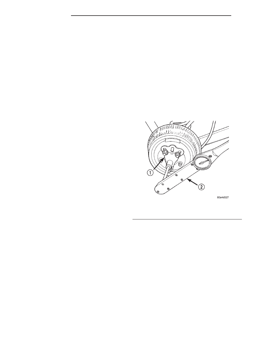
(4) Remove wheel and bolt Special Tool 6790 to

studs.

(5) Use torque wrench on special tool to rotate

wheel and read rotating torque (Fig. 5).

(6) If rotating torque is less than 22 N·m (30 ft.

lbs.) or more than 271 N·m (200 ft. lbs.) on either
wheel the unit should be serviced.

VARI-LOK

TEST

PRIMING

(1) Park the vehicle on a level surface or raise

vehicle on hoist so that the vehicle is level.

(2) Remove the axle fill plug.
(3) Verify that the axle fluid level is correct. The

fluid level is correct if the fluid is level with the bot-
tom of the fill hole.

(4) Shift the transfer case into the 4WD full-time

position.

(5) Drive the vehicle in a tight circle for 2 minutes

at 5mph to fully prime the pump.

Fig. 5 Trac-lok

Y

Test —Typical

1 – SPECIAL TOOL 6790 WITH BOLT IN CENTER HOLE
2 – TORQUE WRENCH

3 - 102

226 RBA AXLE

WJ

DIAGNOSIS AND TESTING (Continued)

TEST PROCEDURE

(1) Block the tires opposite the axle to be tested to

prevent the vehicle from moving.

(2) Shift the transfer case into the 4WD Low posi-

tion and the transmission into the Park position.

(3) Raise both the wheels of the axle to be tested

off of the ground.

(4) Rotate the left wheel by hand at a minimum of

one revolution per second while an assistant rotates
the right wheel in the opposite direction.

(5) The left wheel should spin freely at first and

then increase in resistance within 5 revolutions until
the wheels cannot be continuously rotated in opposite
directions.

(6) The Vari-lok

y differential has engaged prop-

erly if the wheels cannot be rotated in opposite direc-
tions for a moment. After the wheels stop rotating for
a moment, the fluid pressure will drop in the differ-
ential and the wheels begin to rotate once again.

(7) If the system does not operate properly, replace

the Vari-lok

y differential.

SERVICE PROCEDURES

LUBRICANT CHANGE

(1) Raise and support the vehicle.
(2) Remove the lubricant fill hole plug from the

differential housing cover.

(3) Remove the differential housing cover and

drain the lubricant from the housing.

(4) Clean the housing cavity with a flushing oil,

light engine oil, or lint free cloth. Do not use water,
steam, kerosene, or gasoline for cleaning.

(5) Remove the original sealant from the housing

and cover surfaces.

(6) Apply a bead of Mopar

t Silicone Rubber Seal-

ant, or equivalent, to the housing cover (Fig. 6).

Install the housing cover within 5 minutes

after applying the sealant.

(7) Install the cover and any identification tag.

Tighten the cover bolts to 41 N·m (30 ft. lbs.) torque.

(8) For Trac–lok

y and Vari-loky differentials, a

quantity of Mopar

t Trac–loky lubricant (friction

modifier), or equivalent, must be added after repair
service or a lubricant change. Refer to the Lubricant
Specifications section of this group for the quantity
necessary.

(9) Fill differential with correct lubricant to bottom

of the fill plug hole. Refer to the Lubricant Specifica-
tions section of this group for the quantity necessary.

CAUTION: Overfilling the differential can result in
lubricant foaming and overheating.

(10) Install the fill hole plug and lower the vehicle.

(11) Trac–lok

y and Vari-loky differential equipped

vehicles should be road tested by making 10 to 12
slow figure-eight turns. This maneuver will pump the
lubricant through the clutch discs to eliminate a pos-
sible chatter noise complaint.

REMOVAL AND INSTALLATION

REAR AXLE

REMOVAL

(1) Raise and support the vehicle.
(2) Position a suitable lifting device under the

axle.

(3) Secure axle to device.
(4) Remove the wheels and tires.
(5) Remove the brake rotors and calipers from the

axle. Refer to Group 5, Brakes, for proper procedures.

(6) Disconnect parking brake cables from brackets

and lever.

(7) Remove wheel speed sensors, if necessary.

Refer to Group 5, Brakes, for proper procedures.

(8) Disconnect the brake hose at the axle junction

block. Do not disconnect the brake hydraulic lines at
the calipers. Refer to Group 5, Brakes, for proper
procedures.

(9) Disconnect the vent hose from the axle shaft

tube.

(10) Mark the propeller shaft and yokes for instal-

lation alignment reference.

(11) Remove propeller shaft.
(12) Disconnect stabilizer bar links.
(13) Remove nut holding upper suspension arm to

the rear axle ball joint.

(14) Using Remover 8278, separate the rear axle

ball joint from the upper suspension arm (Fig. 7).

Fig. 6 Apply Sealant

1 – SEALANT
2 – AXLE HOUSING COVER

WJ

226 RBA AXLE

3 - 103

DIAGNOSIS AND TESTING (Continued)

(15) Disconnect shock absorbers from axle.
(16) Disconnect track bar.
(17) Disconnect lower suspension arms from the

axle brackets.

(18) Separate the axle from the vehicle.

INSTALLATION

NOTE: The weight of the vehicle must be sup-
ported by the springs before suspension arms and
track bar fasteners can be tightened. If the springs
are not at their normal ride position, vehicle ride
height and handling could be affected.

(1) Raise the axle with lifting device and align coil

springs.

(2) Position the lower suspension arms on the axle

brackets. Install nuts and bolts, do not tighten bolts
at this time.

(3) Install the upper suspension arm to the rear

axle ball joint.

(4) Install nut to hold the upper suspension arm to

the rear axle ball joint. Torque the nut to 122 N·m
(90 ft.lbs.) (Fig. 8).

(5) Install track bar and attachment bolts, do not

tighten bolts at this time.

(6) Install shock absorbers and tighten nuts to 60

N·m (44 ft. lbs.) torque.

(7) Install stabilizer bar links and tighten nuts to

36 N·m (27 ft. lbs.) torque.

(8) Install the wheel speed sensors, if necessary.

Refer to Group 5, Brakes, for proper procedures.

(9) Connect parking brake cable to brackets and

lever.

(10) Install the brake rotors and calipers. Refer to

Group 5, Brakes, for proper procedures.

(11) Connect the brake hose to the axle junction

block. Refer to Group 5, Brakes, for proper proce-
dures.

(12) Install axle vent hose.
(13) Align propeller shaft and pinion yoke refer-

ence marks. Install U-joint straps and bolts. Tighten
to 19 N·m (14 ft. lbs.) torque.

(14) Install the wheels and tires.
(15) Add gear lubricant, if necessary. Refer to

Lubricant Specifications in this section for lubricant
requirements.

(16) Remove lifting device from axle and lower the

vehicle.

(17) Tighten lower suspension arm bolts to 177

N·m (130 ft. lbs.) torque.

(18) Tighten track bar bolts to 100 N·m (74 ft. lbs.)

torque.

PINION SHAFT SEAL

REMOVAL

(1) Raise and support the vehicle.
(2) Remove wheel and tire assemblies.
(3) Remove rear brake rotors and calipers. Refer to

Group 5, Brakes, for proper procedures.

(4) Mark the propeller shaft and pinion yoke for

installation reference.

(5) Remove the propeller shaft from the yoke.
(6) Rotate the pinion gear three or four times.

Fig. 7 Separate Rear Axle Ball Joint

1 – REMOVER
2 – UPPER SUSPENSION ARM
3 – BALL JOINT STUD

Fig. 8 Install Rear Ball Joint Nut

1 – UPPER SUSPENSION ARM
2 – REAR AXLE BALL JOINT
3 – REAR AXLE

3 - 104

226 RBA AXLE

WJ

REMOVAL AND INSTALLATION (Continued)

(7) Measure the amount of torque necessary to

rotate the pinion gear with a (in. lbs.) dial-type
torque wrench. Record the torque reading for instal-
lation reference.

(8) Using a short piece of pipe and Holder 6958 to

hold the pinion yoke, remove the pinion nut and
washer (Fig. 9).

(9) Use Remover C-452 and Wrench C-3281 to

remove the pinion yoke (Fig. 10).

(10) Use Remover 7794-A and slide hammer to

remove the pinion shaft seal (Fig. 11).

INSTALLATION

(1) Apply a light coating of gear lubricant on the

lip of pinion seal. Install seal with Installer C-3972-A
and Handle C-4171 (Fig. 12).

Fig. 9 Pinion Yoke Holder

1 – 1 in. PIPE
2 – PINION YOKE
3 – SPECIAL TOOL 6958
4 – LOWER CONTROL ARM

Fig. 10 Pinion Yoke Removal

1 – SPECIAL TOOL C-3281
2 – YOKE
3 – SPECIAL TOOL C-452

Fig. 11 Seal Removal

1 – SPECIAL TOOL 7794A
2 – SLIDE HAMMER
3 – PINION SEAL

Fig. 12 Pinion Seal Installation

1 – SPECIAL TOOL C-4171
2 – SPECIAL TOOL C-3972–A

WJ

226 RBA AXLE

3 - 105

REMOVAL AND INSTALLATION (Continued)


Content   ..  37  38  39  40   ..