Engine JAC HFC4DA1-2C. Manual - part 65
ET
ET
ET
ET ETACS
ETACS
ETACS
ETACS Body
Body
Body
Body Computer
Computer
Computer
Computer
- 50 -
Diagnosis
Diagnosis
Diagnosis
Diagnosis and
and
and
and Testing
Testing
Testing
Testing
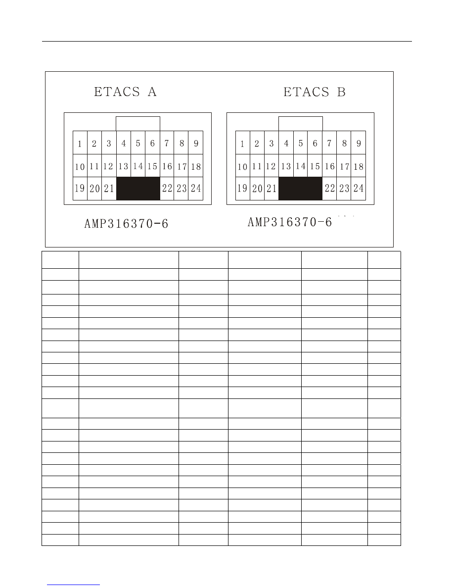
ETACS
ETACS
ETACS
ETACS Pin
Pin
Pin
Pin Definition
Definition
Definition
Definition
Port No.
Port Name
Input/Output
Initial Status
Operating Status
Remark
A1
Interior lamp
Output
High level
Low level
A2
Anti-theft relay
Output
High level (NC)
Low level
Reserved
A3
Front wiper relay
Output
High level
Low level
A4
Rear defroster relay
Output
High level
Low level
A5
Seat belt warning lamp
Output
High level
Low level
A6
Rear fog lamp relay
Output
High level
Low level
A7
Step lamps
Output
NC
Low level
A8
Door locking relay
Output
High level
Low level
A9
A10
B+
A11
Door unlocking relay
Output
High level
Low level
A12
Middle door switch
Input
NC (door closed)
Low level (door
open)
A13
Small lamp relay
Output
High level
Low level
A14
Anti-theft alarm bell
Output
High level
Low level
Reserved
A15
Power window relay
Output
High level
Low level
A16
A17
Front passenger side door switch
Input
NC
Low level
A18
Hazard warning lamp relay
Output
High level
Low level
A19
Ground
A20
Key hole lamp
Output
High level
Low level
A21
A22
A23
(White)
(Gray)