Iveco EuroCargo (12 to 26 t). Manual - part 191


  Index      Iveco     Iveco EuroCargo (12 to 26 t) - service repair manual 2003 year


Search            


Content   ..  189  190  191  192   ..


Iveco EuroCargo (12 to 26 t). Manual - part 191


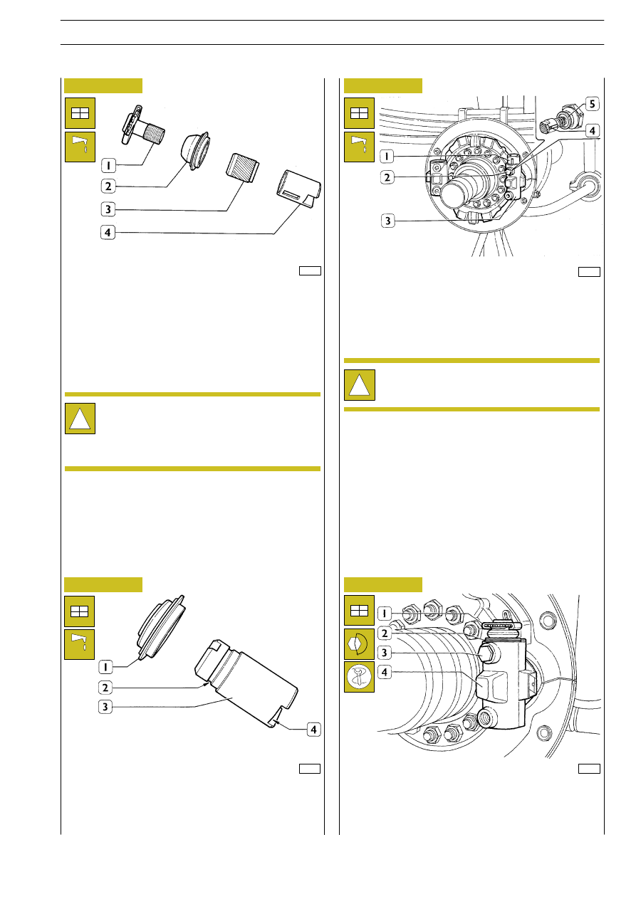
Assemble sealing gaskets (2) on adjustment pins assemblies
(1).
Grease pin (1) threading.
Completely screw adjustment bushes (3) and scrupulously
grease these latter ones on external diameter.
Grease thrust pins (4) internal diameter.

38364

38365

38366

38367

Figure 169

Figure 170

Figure 171

Figure 172

Assemble seaking gaskets (1) on thrust pins (3); make sure of
the correct gaskets profile insertion in thrust pins groove (2).
Grease pins (3) on sliding surface and on wedge (4) sliding
chute.

Insert thrust pin (1) into brake body (3) seat so that the slot
is facing the drive pin (2).
Grease and insert complete guide pin (2) into brake body seat
(3); make sure that washer (5) is inserted and screw some
turns.

Insert automatic adjustment unit (1) into adjustment pin, fit
sealing gasket (2) metal ring on brake body (4).
Lock guide pin (3) at the required torque.

!

During brakes maintenance interventions, replace
sealing gaskets of adjustment and thrust pins.
For lubricating the components, use Rockwell RBSK
0253 grease.

!

Guide pin (2) must be assembled so that prong (4)
slides into suitable brake body (3) hole slot.

E

URO

C

ARGO

T

ECTOR

12-26 t

PNEUMATIC SYSTEM - BRAKES

109

Base - February 2003

38368

38369

38370

17268

35717

Figure 173

Figure 174

Figure 175

Figure 176

Figure 177

By using keyer 99373002 (1), drive sealing gasket metal ring
onto brake body (2).

Insert thrust pin (4) into brake body (1) so that the notch is
facing the guide pin (2) hole.
Grease and screw guide pin (2) at the required torque.

By using keyer 99373002 (2) drive the metal ring (1) of sealing
gasket on brake body.
Proceed as described for assembling the other jaws opening
control units.

Abundantly grease wedge control units (1) and insert them
into their own seat into brake body (2) so that wedge unit
rollers rest on related thrust pins sliding races.

Manually screw ring nut (2) on barrel (1) till its end of stroke.
Apply non-hardenable sealing paste, LOCTITE 573 type, on
first barrel threads.

!

Before proceeding with assembling thrust pins (4),
check the mark punched on them. Letter ”R” (right)
or ”L” (left) shows that the brake belongs to right or
left wheel.

E

URO

C

ARGO

T

ECTOR

12-26 t

110

PNEUMATIC SYSTEM - BRAKES

Base - February 2003

38705

38374

38373

38375

17301

Figure 178

Figure 179

Figure 180

Figure 181

Figure 182

Completely screw brake cylinders (2) into their own seat so
that supply fittings are in their original position and exhaust
hole is open and facing downwards.
Connect brake cylinders supply pipings (1).

Completely screw adjustment unit (2), then unscrew by one
revolution in order to give an initial adjustment for automatic
recovery; place them so that notches (1) allow inserting the
jaws.

Assemble jaws (1) into their suitable seat so that the punched
arrow (2) is oriented along the forward-running drum rotation
direction.
Hook jaws return springs (3 and 5) using tool 99372217 (4).

Operate on adjustment units (1 and 2) till a dimension (A) is
obtained, measured with a gauge, that is by 2 mm lower than
the one detected on the used drum.

Lubricate bearings seat on barrel (3) and wheel hub sealing ring
with TUTELA W 140/MDA oil.
By using hydraulic trolley 99321024 (1), place complete wheel
(2) so that internal hub diameter is perfectly centred on rear
axle case barrel (3). Place tapered roller bearing (4) into wheel
hub. Insert complete wheel till the end of its seat, taking care
of aligning wheel hub with barrel (3) to avoid damaging sealing
gaskets profiles.

E

URO

C

ARGO

T

ECTOR

12-26 t

PNEUMATIC SYSTEM - BRAKES

111

Base - February 2003

35768

35770

35771

35772

Figure 183

Figure 184

Figure 185

Figure 186

Figure 187

Figure 188

Screw locking ring nut and tighten it through wrench
99355167 (1) and dynamometric wrench (2) at the required
torque.

35768

Screw locking ring nut and tighten it through wrench 99355167
(1) and dynamometric wrench (2), tighten adjustment nut at
a torque of 98 Nm (10 kgm); at the same time, rotate hub along
the two directions.
Then loosen the nut down to a zero torque.
Further unscrew the nut till an axial clearance is obtained that
is included between 0.20 and 0.30 mm, corresponding to an
angular movement of about 1/6 of a revolution.

Assemble the safety ring (2): if the nut (1) stop dowel does not
coincide with one of the safety ring (2) holes, change nut (1)
position taking also into account the clearance obtained in the
previous operation.

35769

Place comparator (1) with magnetic base on hub (3). Abut rod
onto barrel (2) and check that maximum axial hub clearance is
0.05 mm.

Assemble half-shaft (1), insert securing screws (2) and tighten
them at the required torque.

Butter with hermetic type ”B” the contact surface (1) between
half-shaft and wheel hub.

E

URO

C

ARGO

T

ECTOR

12-26 t

112

PNEUMATIC SYSTEM - BRAKES

Base - February 2003


Content   ..  189  190  191  192   ..