Iveco EuroCargo (12 to 26 t). Manual - part 89


  Index      Iveco     Iveco EuroCargo (12 to 26 t) - service repair manual 2003 year


Search            


Content   ..  87  88  89  90   ..


Iveco EuroCargo (12 to 26 t). Manual - part 89


84469

84470

84471

84472

84473

Figure 35

Figure 36

Figure 37

Figure 38

Figure 39

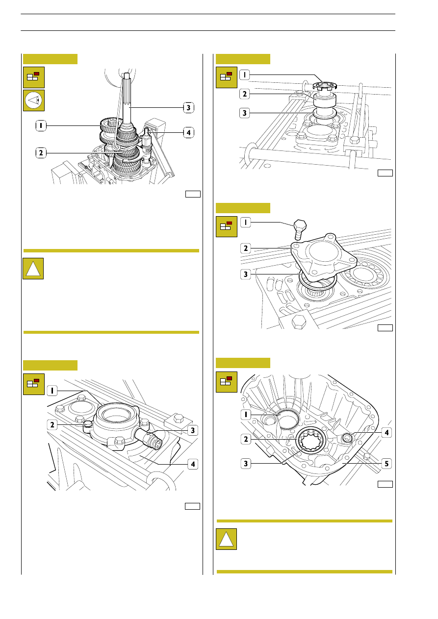
Secure output shaft (2) with a rope, then lift it by about 20 mm
by means of a hoist so as to be able to move away countershaft
(1) and remove the motion inlet shaft (3) and the underlying
synchronizing ring and the roller bearing.

Turn rear half case (4) upside down.
Remove revs sensor (3).
Remove screws (2) and take off cover (1).

Remove phonic wheel (1), spacer (2) and ring (3) of roller
bearing.

Remove screws (1), take off cover (2) and remove spacer (3).

Remove the following items from rear half case (5): bushing
(4) supporting the fork supporting shaft, the tapered-roller
bearing outer race (1) and roller bearing outer race (2).

!

This operation must be performed with the greatest
care to prevent the ends of output shaft (2) and of
fork supporting shaft (4) from jamming in the relevant
bearing or support bushing.
Take output shaft (2) out of the rear half case, remove
fork supporting shaft (4) from the output shaft, then
place both shafts on a suitable container.
Remove countershaft (1).

!

When removing outer race (2), pay attention to the
possible escape of rollers (3) of the same from their
own seat.
Repeat the same operations on the front half case.

GEARBOX EATON FSO 5206B

E

URO

C

ARGO

T

ECTOR

12-26 t

206

Base - February 2003

84474

84475

Figure 40

Figure 41

PARTS MAKING UP THE MOTION INLET SHAFT

1. Snap ring - 2. Spacer ring - 3. 4. 5. Cylindrical roller bearing - 6. Motion inlet shaft - 7. Matching body

Use ordinary tools to take the cylindrical roller bearing inner
race (5) and matching body (7) off the motion inlet shaft (6).

Assembling

Heat roller bearing inner race (5) to ~ 85

°C, then

fit it onto motion inlet shaft (6).
Apply LOCTITE 648 on inner teeth (

→) of matching

body (7), then mount the latter onto motion inlet
shaft (6).

Take 5

th

- 6

th

gear engagement sliding sleeve (2) off hub (1);

pay attention to the escape of rollers (3), pins (4) and springs
(5), then recover the same.

Remove snap ring (6).

OUTPUT SHAFT
Disassembling

!

All snap rings are provided with replacement parts of
different thickness in order to obtain correct
assembly play. Snap rings must be disassembled and
re-assembled with care so as not to score the output
shaft surface.
Prior to taking apart the output shaft, verify that the
axial play of every single gear falls within the
prescribed values.
Take note of the assembling position of synchronizers
- matching bodies, hubs and sliding sleeves, so as to
be able to fit them back in the same positions.

GEARBOX EATON FSO 5206B

E

URO

C

ARGO

T

ECTOR

12-26 t

207

Base - February 2003

Turn the output shaft upside down.
Use an extractor made up of bridge 99341003 (1), tie bars
99341019 (7), grips 99341025 (2) and clamp 99341015 (6),
to remove reverse gear (5), shoulder ring (4) and roller
bearing inner race (3), then take out the roller bearing below.

84476

84478

84477

33628

33629

84479

Figure 42

Figure 43

Figure 44

Figure 45

Figure 46

Figure 47

Remove hub (5) with the synchronizer (6) below, by means
of an extractor made up of bridge 99341003 (1), brackets
99341019 (2), grips 99341025 (4) and clamp 99341015 (3).

Take off matching body (1), 6

th

speed gear (2) and roller cage

(3).
Remove snap ring (4).

Take off snap ring (1).

Use an extractor made up of grips 99341023 (4), tie bars
99341020 (6), bridge 99341003 (1) and clamp 99341015 (5)
to remove 1

st

speed gear (3) and fixed hub (2) for reverse

gear.

Remove matching body (1), inner ring (2), intermediate ring
(3), synchronizing ring (4) and roller cage (5).

GEARBOX EATON FSO 5206B

E

URO

C

ARGO

T

ECTOR

12-26 t

208

Base - February 2003

84480

84481

84482

84483

Figure 48

Figure 49

Figure 50

Figure 51

Take 1

st

- 2

nd

gear engagement sliding sleeve (2) off hub (1);

pay attention to the escape of balls (5), springs (3) and dowels
(4), then recover the same. Remove dowels (6) and take off
snap ring (7).

Use a hydraulic press to remove 1

st

speed gear (7) together

with matching body (6), synchronizing ring (3), intermediate
ring (4), ring (5) and hub (2) from output shaft (1).

Turn output shaft (1) upside down. Remove snap ring (2). Use
a hydraulic press to remove 4

th

speed gear (11), matching

body (10), synchronizing ring (6), synchronizing unit (8),
synchronizing ring (7), matching body (6), 3

rd

speed gear (5),

roller cage (4) and bushing (3).

Take 3

rd

- 4

th

gear engagement sliding sleeve (2) off hub (1);

pay attention to the escape of hub of rollers (3), pins (2) and
springs (5), then recover the same.

GEARBOX EATON FSO 5206B

E

URO

C

ARGO

T

ECTOR

12-26 t

209

Base - February 2003


Content   ..  87  88  89  90   ..