Iveco EuroCargo (12 to 26 t). Manual - part 27
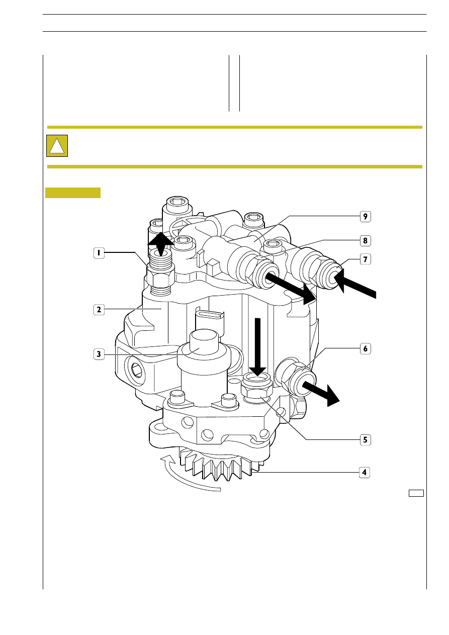
Figure 210
72595
1. Fuel outlet fitting to rail - 2. High-pressure pump - 3. Pressure regulator - 4. Control gear - 5. Fuel inlet fitting from filter -
6. Fuel outlet fitting to filter support - 7. Fuel inlet fitting from control unit heat exchanger - 8. Fuel outlet fitting from supply
pump to filter - 9. Mechanical supply pump
Pump with 3 radial pistons controlled by the timing gear,
without needing any setting. On the rear side of the high
pressure pump is fitted the mechanical supply pump
controlled by the high pressure pump shaft.
CP3 HIGH-PRESSURE PUMP
!
The high pressure pump-mechanical supply pump unit cannot be overhauled and therefore it must not be disassembled
nor its fastening screws must be tampered with.
The only admitted operation is control gear replacement.
E
URO
C
ARGO
T
ECTOR
12-26 t
ENGINE F4 AE 0481
105
Base - February 2003