Engine Iveco C10/C13/C78/Cursor 13/Cursor 78. Manual - part 20
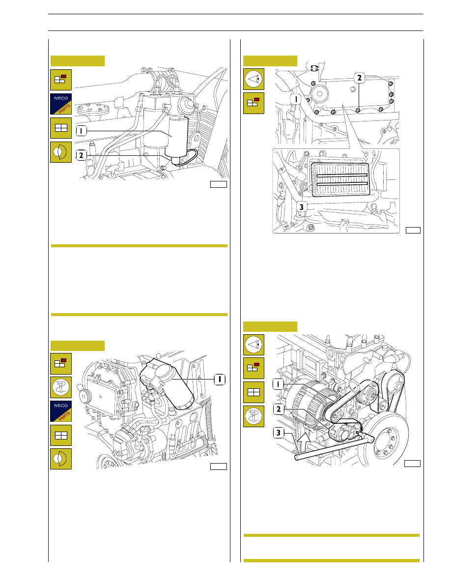
Figure 106
108395
Replace fuel sedimentation tank prefilter (when it is
required by the application)
Disconnect electric connector. Unlock prefilter (1) and
change it. Before refitting a new cartridge, wet seal with fuel
oil or engine oil. Lock cartridge by hand till in contact with
support, then lock it by
¾ of a rev. at predefined tightening
torque.
At change, filter cartridge must not be prefilled to
prevent
circulating
dirt
that
could
damage
injector/pump system components. Bleed air from
fuel filter as described in previous pages.
Figure 107
112859
Fuel filter change
Use tool 99360314 to remove fuel filter (1).
Before fitting the new cartridge, wet seal with fuel oil or engine
oil. Lock the new one by hand and carefully check that rubber
seal and contact surface are clean and in perfect conditions.
Lock cartridge by hand till contact with support and then lock
it for
¾ of a rev. at prescribed tightening torque. Bleed air from
supply system as described in paragraph below:
Check Blow-by filter conditions by means of a clogging
indicator
Figure 108
72563
- Check filter (3) conditions by means of a clogging
indicator (1). In case the red area appears, change it.
- For screw (2) change, remove carter, pull out filter (3) and
replace it with a new one. Filter has a one-way operation,
therefore it must be installed with the two reinforcement
bars visible, as shown in the picture.
Check of water pump/alternator control belt condition
Figure 109
107903
Visually check that belt (1) is not worn out or broken; change
it as described below, if required.
Water pump/alternator control belt change
In order to remove and refit belt (1), operate using a specific
tool (3) on belt tensioner (2) in direction shown by arrow.
Belt tensioner is
automatic and requires no
adjustment.
NOTE
NOTE
SECTION 3 - INDUSTRIAL APPLICATION
61