Engine Iveco C10/C13/C78/Cursor 13/Cursor 78. Manual - part 15
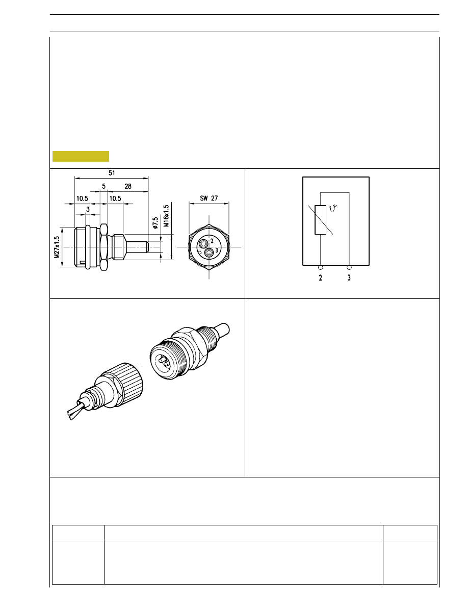
TECHNICAL VIEW
8527
000602t
WIRING DIAGRAM
PERSPECTIVE VIEW
000693t
Figure 98
SECTION 3 - INDUSTRIAL APPLICATION
37
Engine coolant temperature sensor
This N.T.C. type sensor located on the water outlet sump on the engine head left measures coolant temperature for the various
operating logics with a hot or cold engine and identifies injection enrichment requirements for a cold engine or fuel reduction
requirements for a hot engine.
It is connected to electronic center pins A5/A22.
Sensor behavior as a function of temperature:
- 10
°C
8,10
÷ 10,77 kOhm
+ 20
°C
2,28
÷ 2,72 kOhm
+ 80
°C
0,29
÷ 0,364 kOhm
At 60 to 90 _C, voltage at A5 and A22 ranges from 0.6 to 2.4V.
Connector
Function
Cable colour
2
To EDC center pin A 5
–
3
To EDC center pin A 22
–