Content .. 997 998 999 1000 ..
Isuzu Amigo / Axiom / Trooper / Rodeo / VehiCross. Manual - part 999
8F–46
BODY STRUCTURE
Cross Beam Assembly
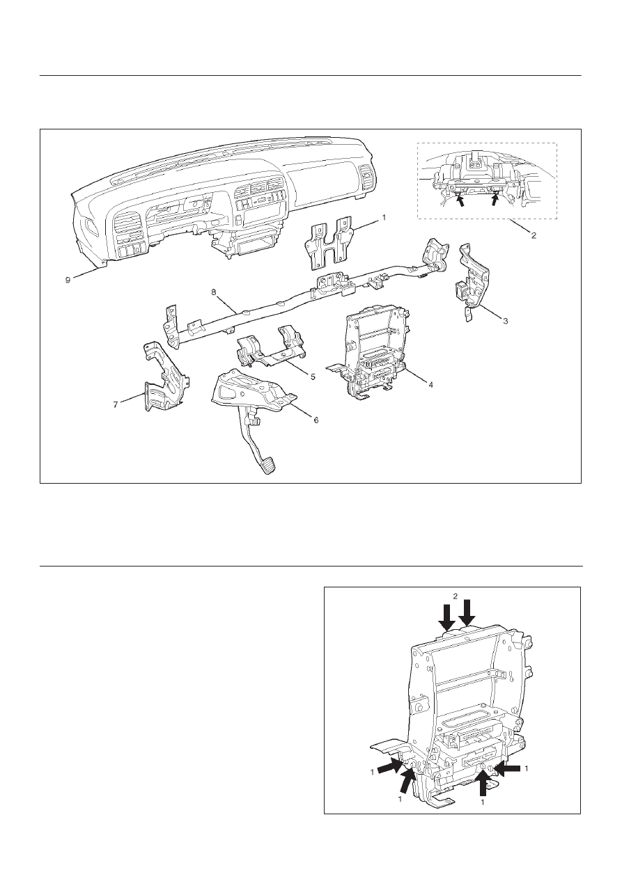
Parts Location
740RT013
Legend
(1) Cross Beam Center Bracket
(2) Steering Column Fixing Bolts
(3) Side Support Bracket Assembly (RH)
(4) Instrument Panel Center Bracket
(5) Steering Support Bracket Assembly
(6) Brake Pedal Mounting Bracket Assembly
(7) Side Support Bracket Assembly (LH)
(8) Cross Beam Assembly
(9) Instrument Panel Assembly
Removal
1. Disconnect battery ground cable.
2. Remove instrument panel assembly.
D
Refer to Instrument Panel Assembly in this section.
3. Remove side support bracket assembly (LH/RH).
D
Remove the 4 fixing bolts on both sides.
4. Remove cross beam center bracket
D
Remove 2 fixing nuts.
5. Remove instrument panel center bracket.
D
Disconnect the PCM and EBCM connector.
D
Remove the DERM (SRS) with 3 fixing nuts.
CAUTION: For precautions on installation or
removal of SRS — air bag system, refer to
Supplemental Restraint System (SRS) — AIR BAG in
Restraint section.
D
Remove the 2 fixing nuts (upper) and the 4 fixing
bolts (lower).
740RT010