Isuzu Amigo / Axiom / Trooper / Rodeo / VehiCross. Manual - part 928


  Index      Isuzu     Isuzu Amigo / Axiom / Trooper / Rodeo / VehiCross - service repair manual 1999-2002 year


Search            


Content   ..  926  927  928  929   ..


Isuzu Amigo / Axiom / Trooper / Rodeo / VehiCross. Manual - part 928


7A1–32 TRANSMISSION CONTROL SYSTEM (4L30–E)

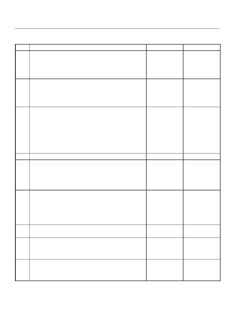
DTC P0706 Transmission Range Switch (Mode Switch) Performance 

Step

Action

Yes

No

1

Were you sent here from the “Powertrain On–Board Diagnostic
(OBD) System Check”?

Go to Step 2

Go to OBD

System Check

Refer to

Driveability and

Emissions in

Engine section

2

Perform the following checks:

D

The transmission linkage from the select lever to the manual
valve is adjusted properly.

D

Diagnostic circuit check.

Were the checks performed?

Go to Step 3

3

1. Install the scan tool.
2. With the engine “off”, turn the ignition switch “on”.

NOTE: Before clearing DTC(s), use the scan tool to record “Freeze
Frame” and “Failure Records” for reference, as data will be lost
when the “Clear Info” function is used.

3. Record the DTC “Freeze Frame” and “Failure Records”.
4. Select each transmission range:  D1, D2, D3, D4, N, R, and P.

Does each selected transmission range match the scan tool
“Range Switch” display?

Go to Diagnostic

Aids

Go to Step 4

4

Are all range switch pin displays incorrect?

Go to Step 5

Go to Step 6

5

Check fuse and wiring to the 8–way connector terminal 5(D) for
opens.
Refer to Mode Switch in Automatic Transmission (4L30–E)
section.
If no problem was found, replace the range switch.

Is the replacement complete?

Go to Step 9

6

1. Disconnect the 8–way range switch connector.
2. Using ohmmeter, check continuity between terminal 5(D) and

respectively terminals 3(G), 6(C), 7(B) and 8(A) of the 8–way
range switch connector.

3. Move shift selector lever through all positions and compare

results with “Range Switch Logic Table”.

Is one range switch pin display incorrect?

Go to Step 7

Go to Step 8

7

Check the affected wiring and connector, and repair.

Is the repair complete?

Go to Step 9

8

Check the Powertrain Control Module (PCM) connectors for poor
connection.
If no problem was found, replace the PCM.

Is the replacement complete?

Go to Step 9

9

1. After the repair is complete, use the scan tool to select “DTC”,

then “Clear Info” function and road test the vehicle.

2. Review the scan tool “DTC Info”.

Has the last test failed or is the current DTC displayed?

Begin diagnosis

again

 Go to Step 1

Repair verified
Exit DTC table

TRANSMISSION CONTROL SYSTEM (4L30–E)

7A1–33

DTC P0711 Transmission Fluid Temperature (TFT) Sensor Performance

D07RY00010

Circuit Description

The TFT sensor is a thermister that controls the signal
voltage to the PCM. The PCM supplies a 5–volt reference
signal to the sensor on circuit RED/WHT. When the
transmission fluid is cold, the sensor resistance is high
and the PCM detects high signal voltage. As the
transmission fluid temperature increases to normal
operating temperature of 100

°

C (212

°

F), the sensor

resistance becomes less and the voltage decreases to
1.5 to 2 volts.
When the PCM detects a TFT sensor that remains at the
startup value, or a sensor that has a change delta of
greater than 20

°

C (36

°

F) less than 1 second, DTC P0711

sets. DTC P0711 is a type D.

Conditions For Setting The DTC

D

No VSS DTCs P0722 or P0723.

D

No Transmission Component Slipping DTC P1870.

D

Engine is running.

D

TFT is between 20 A/D (Analog/Digital) counts and
248 A/D counts.

D

TFT is between –40

°

C (–40

°

F) and +21

°

C (69.8

°

F)

at engine startup.

D

Engine coolant temperature is greater than 70

°

C

(150

°

F).

D

Engine coolant temperature has changed by greater
than 50

°

C (90

°

F) since engine startup.

D

Vehicle speed has been greater than 5 mph for
greater than 410 seconds since engine startup
(cumulative timer).

D

TCC slip speed has been greater than 120 rpm for
greater than 410 seconds since engine startup
(cumulative timer).

D

Battery voltage is between 10 and 16 volts.

All of the above is true and either of the following occurs:

D

If the sensor is stuck, the TFT has not changed for
greater than 2 counts (from startup temperature) for
greater than 410 seconds.

D

If the sensor shows an unrealistic change, the TFT
exhibits a change delta of greater than 20

°

C (36

°

F),

greater than 14 times in 7 seconds.

Action Taken When The DTC Sets

D

Transmission default temperature will be:

80

°

C (176

°

F) if engine temperature code is set.

100

°

C (212

°

F) if engine temperature is warm.

80

°

C (176

°

F) if engine run time is greater than 5

minutes.

21

°

C (69.8

°

F) if engine run time is less than 5

minutes.

D

The PCM will not illuminate the Malfunction Indicator
Lamp (MIL).

Conditions For Clearing The DTC

D

The DTC can be cleared from the PCM history by
using a scan tool.  

D

The DTC will be cleared from history when the vehicle
has achieved 40 warmup cycles without a failure
reported.

D

The PCM will cancel the DTC default actions when
the fault no longer exists and the ignition is cycled “off”
long enough to power down the PCM.

Diagnostic Aids

D

Inspect the wiring for poor electrical connection at the
PCM. Inspect the wiring for poor electrical
connections at the transmission 16–way connectors.
Look for the following conditions:

a. A bent terminal
b. A backed out terminal
c. A damaged terminal
d. Poor terminal tension
e. A chafed wire
f. A broken wire inside the insulation

7A1–34 TRANSMISSION CONTROL SYSTEM (4L30–E)

D

When diagnosing for an intermittent short or open
connection, move the wiring harness while watching
the test equipment for a change.

D

First diagnose and clear any engine DTCs or TP
Sensor codes. Then inspect for any transmission
DTCs that may have reset.

Test Description

The number below refers to the step number on the
diagnostic chart:
3. This test checks PCM and associated wiring up to

the 16–way connectors. If the voltage increases to
match chart the problem is isolated to the
transmission wiring.

Resistance Chart

°

C

°

F

Resistance (k

W

)

–40

–40

672

0

32

65

20

68

25

80

176

2.5

120

248

0.78

150

304

0.37

DTC P0711 Transmission Fluid Temperature (TFT) Sensor Performance 

Step

Action

Yes

No

1

Was the Powertrain On–Board Diagnostic (OBD) System Check
performed?

Go to Step 2

Go to OBD

System Check

Refer to

Driveability and

Emissions in

Engine section

2

Perform the transmission fluid checking procedure.  Refer to
Checking Transmission Fluid Level and Condition in Automatic
Transmission (4L30–E) section.

Did you perform the fluid checking procedure?

Go to Step 3

Go to Checking

Transmission

Fluid Level and

Condition in

Automatic

Transmission

(4L30–E) section

3

1. Install the scan tool.
2. With the engine “off”, turn the ignition switch to the “on”

position.

NOTE: Before clearing DTCs, use the scan tool in order to record
the Freeze Frame and Failure Records for reference. The Clear
Info function will erase the data. 

3. Record the DTC Freeze Frame and Failure Records.
4. Select TFT on the scan tool.
5. While observing the scan tool display, move or massage the

engine wiring harness from PCM connectors J2–66 and J2–20
to the transmission 16–way connectors.

Does the TFT change by more than 

±

20

°

C (36

°

F)?

Go to Step 6

Go to Step 4

4

1. Turn the ignition “off”.
2. Disconnect the transmission 16–way connector H–56.
3. Install Jumper Harness on the transmission side of the

16–way connector H–56.

4. Using the J39200 DVOM and J35616 Connector Test Adapter

Kit, connect the DVOM leads from terminal M7–4(F) to
terminal M7–1(E).

5. Set the DVOM on MIN/MAX to measure resistance.
6. Record the TFT sensor resistance.
7. Move or massage the automatic transmission wiring harness

assembly from the 16–way connector H–56 to the TFT sensor
connector.

Does the DVOM MAX display a resistance greater than the value
recorded in Action item 6 of this step?

Go to Step 7

Go to Step 5

5

Does the DVOM MIN display a resistance less than the value
recorded in Action item 6 of step 4?

Go to Step 8

TRANSMISSION CONTROL SYSTEM (4L30–E)

7A1–35

DTC P0711 Transmission Fluid Temperature (TFT) Sensor Performance  (Cont’d)

Step

No

Yes

Action

6

Inspect circuit RED/WHT and RED/BLK of the engine wiring
harness for an intermittent open or short condition. Repair the
circuits if necessary.

Did you find a problem?

Go to Step 12

Go to Step 11

7

Inspect the automatic transmission wiring harness assembly for
an intermittent open in circuits RED/WHT and RED/BLK.

Did you find a problem?

Go to Step 9

Go to Step 10

8

Inspect the automatic transmission wiring harness assembly for
an intermittent shorted condition in circuits RED/WHT and
RED/BLK.

Did you find a problem?

Go to Step 9

Go to Step 10

9

Replace the automatic transmission wiring harness assembly.

Is the replacement complete?

Go to Step 12

10

Replace TFT Sensor. Refer to Transmission Oil Temperature
Sensor (Main Case)
 in Automatic Transmission (4L30–E)
section.

Is the replacement complete?

Go to Step 12

11

Replace the PCM. Refer to Powertrain Control Module (PCM) in
Automatic Transmission (4L30–E) section.

Is the replacement complete?

Go to Step 12

12

In order to verify your repair, perform the following procedure.
1. Select DTC.
2. Select Clear Info.
3. Drive the vehicle and ensure the following conditions are met:

D

The TFT changes by more than 2.25

°

C (4.05

°

F) for 11

seconds since startup.

D

The TFT does not change by more than 20

°

C (36

°

F) within

0.200 second for a period of at least 11 seconds.

4. Select Specific DTC.
5. Enter DTC P0711.

Has the test run and passed?

System OK

Begin the

diagnosis again

 Go to Step 1


Content   ..  926  927  928  929   ..