Isuzu Amigo / Axiom / Trooper / Rodeo / VehiCross. Manual - part 924


  Index      Isuzu     Isuzu Amigo / Axiom / Trooper / Rodeo / VehiCross - service repair manual 1999-2002 year


Search            


Content   ..  922  923  924  925   ..


Isuzu Amigo / Axiom / Trooper / Rodeo / VehiCross. Manual - part 924


7A1–16 TRANSMISSION CONTROL SYSTEM (4L30–E)

060R200253

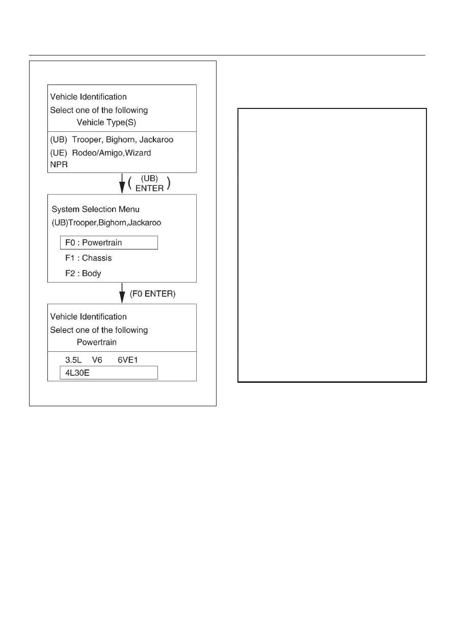
Once the test vehicle has been identified an “Application
(Powertrain) Menu” screen appears. Please select the
appropriate application.
The following table shows, which functions are used for
the available equipment versions.

F0: Diagnostic Trouble Codes

F0: Read DTC Info Ordered By Priority

F1: Clear DTC Information

F2: DTC Information

F1: Data Display

F0: Transmission Data

F1: Output Driver Data

F2: Snap Shot

F3: Actuator Tests

F0: Lamps

F0: Check Light

F1: Winter Drive Lamp

F2: Power Drive Lamp

F3: AT Oil Temperature Lamp

F1: Solenoids

F0: Solenoid 1-2/3-4 Test

F1: Solenoid 2-3 Test

F2: TCC Solenoid

F3: Band Apply Solenoid

F4: Pressure Control Solenoid (PCS)

F4: Function Tests

F0: Reset Oil Life Monitor

TRANSMISSION CONTROL SYSTEM (4L30–E)

7A1–17

Diagnostic Trouble Codes
The purpose of the “Diagnostic Trouble Codes” mode is to
display stored PCM trouble codes.
When  “Diagnostic Trouble Codes” is selected an
“Application Menu” screen appears.

Clear DTC Information
The purpose of the “Clear DTC Information” mode is to
command the clearing of stored PCM trouble codes.
When “Clear DTC Information” is selected, a “Clear DTC
Information”, warning screen appears. This screen
informs you that by cleaning DTC’s,  “all stored DTC
information in controller will be erased”.
Do you want to clear DTC’s (Yes/No).
Press either the Yes or No key when answering.
After clearing codes, confirm system operation by test
driving the vehicle.
Allow the vehicle to shift through all four forward gears in a
manner which attempts to repeat the failure condition.

NOTE: When the trouble has not been repaired and the
trouble code cannot be erased, check the vehicle again.

DTC Information
When  “DTC Information” is selected, an “Application
Menu” appears with a list of DTC information function
keys addressing DTC specifics and their origins.
Function key selections may vary for particular vehicle
and/or system.

Data Display
The purpose of the “Data Display” mode is to
continuously monitor data parameters.
The current actual values of all important sensors and
signals in the system are display through F1 mode.
When “Data Display” is selected an “Application Menu”
appears. Please select either “Engine” or “Transmission
Data Display”.
See “Transmission Data” on next page.

Snapshot
When  “Snapshot” is selected an “Application Menu”
appears.
When  “Transmission Snapshot” application is selected
from the “Application Menu”, a “Snapshot Menu”
appears, displaying several options. “Snapshot” options
may vary from one system to another.
“Snapshot” allows a recording of all vehicle parameters.
There parameters may then be replayed at a future point
in time.
This action allows you to focus on making the condition
occur, rather than trying to view all of the data in
anticipation of the fault. The snapshot will collect
parameter information around a trigger point that you
select.
When a snapshot is taken. It is recorded onto the
PCMCIA memory card. When the Tech 2 is powered
down. Snapshots are not lost.

Actuator Tests
The purpose of “Actuator Tests” mode is to check for
correct operation of electronic system actuators.

Lamps
You can operate the lamps by pressing the ON and OFF
buttons.

Preconditions: none

Solenoid
Solenoid 1-2/3-4, Solenoid 2-3, TCC Solenoid
You can operate the solenoids by pressing the ON and
OFF buttons.
Preconditions: P–N position, no vehicle speed, no engine
speed
Band Apply Solenoid
You can operate the solenoid by pressing the ON and
OFF buttons.
Preconditions: P-N position, idle engine speed, no vehicle
speed.
Pressure Control Solenoid (PCS)
You can set desired PCS Current using the UP (+25) and
DOWN (–25) button. The PC Solenoid Data informs
about PCS Current, Pressure and Duty Cycle.
Preconditions: P–N position, no engine speed, no vehicle
speed

Reset Oil Life Monitor
Displays parameter “Oil Life Monitor” and resets to 100%
if Yes-button is pressed on Reset-question. “No” leaves
test.
Preconditions: no vehicle speed, no engine speed

7A1–18 TRANSMISSION CONTROL SYSTEM (4L30–E)

Transmission Data

Item

Unit

Engine running at idle

Ignition Voltage

V

12.8 

 14.1 V

Engine Speed

RPM

750 

 900 RPM

Vehicle Speed

km/h, MPH

0 MPH

AT Output Speed (Automatic Transmission)

RPM

0 RPM

AT Input Speed Ratio (Automatic Transmission)

0.0

Throttle Position

%

0 %

AT Oil Temperature (Automatic Transmission)

°

C, 

°

F

70 

 80

°

C (158 

 176

°

F)

Transmission Temperature

°

C, 

°

F

75 

 110

°

C (167 

 230

°

F)

AT Oil Temperature Lamp (Automatic Transmission)

Off, On

Off

AT Oil Life Monitor (Automatic Transmission)

%

100 %

AT Oil Life Lamp (Automatic Transmission)

Off, On

Not used

Commanded Gear

1

Current Gear

1

Mode Switch A

Inactive, Active

Active

Mode Switch B

Inactive, Active

Inactive

Mode Switch C

Inactive, Active

Inactive

Mode Switch G

Inactive, Active

Active

Selector Position

Park

1–2 Shift Solenoid A

Off, On

Off

2–3 Shift Solenoid B

Off, On

On

Solenoid Brake Band

Off, On

Off

TCC Slip Speed

RPM

750 

 900 RPM

TCC Solenoid

Off, On

Off

TCC Duty Cycle

%

0 %

PCS Current (Pressure Control Solenoid)

A

approx. 1.0 A

PCS Duty Cycle (Pressure Control Solenoid)

%

approx. 45 %

Desired PCS Pressure (Pressure Control Solenoid)

kPa

43 

 52 kPa

Shift Pressure

kPa

43 

 52 kPa

Brake Switch

Off, On

On

Kickdown Switch

On, Off

Not used

Winter Switch

On, Off

Off

Winter Drive Lamp

Off, On

Off

Power Switch

Power Drive Nor-

mal

Normal

Power Drive Lamp

Off, On

Off

Emergency Mode

Off, On

Off

ABS Status

On, Off

Off

TRANSMISSION CONTROL SYSTEM (4L30–E)

7A1–19

OBD II Diagnostic Management System

Powertrain Control Module (PCM) Location

826RY001

826RY002

Class 2 Serial Data Bus
OBD II technology requires a much more sophisticated
PCM than does OBD I technology. The OBD II PCM
diagnostic management system not only monitors
systems and components that can impact emissions, but
they also run active tests on these systems and
components. The decision making functions of OBD II
PCMs have also greatly increased. To accommodate this
expansion in diagnostic complexity, Isuzu engineers have
designed the Class 2 serial data bus, which meets SAE
J1850 recommended practice for serial data.
“Serial Data” refers to information which is transferred in a
linear fashion – over a single line, one bit at a time. A “Data
Bus” is an electronic pathway through which serial data
travels.

TROOPER previously used a 5 volt data bus called
UART, which is an acronym for “Universal Asynchronous
Receive and Transmit”. When neither the vehicle’s
control module nor the diagnostic tool, such as a Tech 2,
are “talking,” the voltage level of the bus at rest is 5 volts.
The two computers talk to each other at a rate of 8,192
bits per second, by toggling or switching the voltage on
the data bus from 5 volts to ground.
Class 2 data, which is used on OBD II vehicles, is quite
different. Data is transferred at a rate of 10.4 kilobits per
second, and the voltage is toggled between zero and 7
volts.


Content   ..  922  923  924  925   ..