Isuzu Amigo / Axiom / Trooper / Rodeo / VehiCross. Manual - part 890


  Index      Isuzu     Isuzu Amigo / Axiom / Trooper / Rodeo / VehiCross - service repair manual 1999-2002 year


Search            


Content   ..  888  889  890  891   ..


Isuzu Amigo / Axiom / Trooper / Rodeo / VehiCross. Manual - part 890


6G–4

ENGINE LUBRICATION

11. Remove drive gear.

12. Remove oil seal.
13. Remove O-ring.

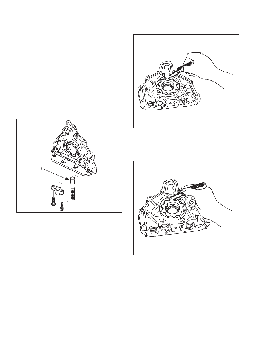
Inspection and Repair

CAUTION: Make necessary correction or parts
replacement if wear, damage or any other abnormal
conditions are found during inspection.

Relief Valve (8)

D

Check to see that the relief valve slides freely.

D

The oil pump must be replaced if the relief valve does
not slide freely.

D

Replace the spring and/or the oil pump assembly (5) if
the spring is damaged or badly worn.

051RS002

Body (14) and Gears (10, 11)

The pump assembly must be replaced if one or more of
the conditions below is discovered during inspection.

D

Badly worn or damaged driven gear (10).

D

Badly worn drive gear (11) driving face.

D

Badly scratched or scored body sliding face (14) or
driven gear (10).

D

Badly worn or damaged gear teeth.

Measure the clearance between the body and the driven
gear with a feeler gauge.

Standard : 0.10 mm–0.18 mm

(0.0039 in.–0.0070 in)

Limit : 0.20mm (0.0079 in)

051RS004

D

Measure the clearance between the drive gear and
driven gear with a feeler gauge.

Standard : 0.11 mm–0.24 mm

(0.0043 in–0.0094 in)

Limit : 0.35mm (0.0138 in)

051RS003

D

Measure the side clearance with a precision straight
edge and a feeler gauge.

Clearance
Standard : 0.03 mm–0.09 mm

(0.0011 in–0.0035 in)

Limit : 0.15mm (0.0059 in)

6G–5

ENGINE LUBRICATION

051RS005

Oil Strainer

Check the oil strainer for cracking and scoring. If cracking
and scoring are found, the oil strainer must be replaced.

051RS006

Reassembly

1. Install drive gear (11).
2. Install driven gear (10).
3. Install oil pump cover (9) and first, loosely tighten all of

the attaching screws. Next, tighten the attaching
screws to the specified torque.

Torque : 10 N·m (89 lb in)

After installation, check that the gear rotates
smoothly.

4. Install relief valve (8) and apply engine oil to the relief

valve and spring (7).

5. Install spring (7).

6. Install the plug (6).

Torque : 8 N·m (69 lb in)

051RS007

7. Install oil pump assembly (5).

D

Carefully remove any oil from the cylinder body and
the pump. Apply sealant (TB–1207B or equivalent)
to the pump fitting face as shown in illustration. Take
care that sealant is not applied to oil port surfaces.
The oil pump assembly must be installed within 5
minutes after sealant application before the sealant
hardens.

CAUTION: Do not apply an excessive amount of
sealant to the contact surface. Applying too much
sealant will overflow the contact surfaces. This
could cause serious damage to the engine.

D

Attach oil pump assembly to cylinder body.

D

Tighten the oil pump fixing bolts.

Torque : 25 N·m (18 lb·ft)

051RW002

6G–6

ENGINE LUBRICATION

051RW001

Legend

(1) Around Bolt Holes
(2) Around Dowel Pin

8. Install the new oil seal (12). Apply engine oil to the oil

seal lip before installation then use J–39202 oil seal
Installer, install oil seal.

015RS001

9. Install oil strainer (4) with O-ring (13).

Torque: 25 N·m (18 lb ft)

10. Install oil pipe (3) with O-ring (13).

Torque: 25 N·m (18 lb ft)

11. Install crankcase with oil pan (2).

D

Remove oil on crankcase mounting surface and dry
the surface.

D

Apply a proper 4.5 mm (0.7 in) wide bead of sealant
(TB1207C or equivalent) to the crankcase
mounting surface. The bead must be continuous.

D

The crankcase must be installed within 5 minutes
after sealant application before the sealant
hardens.

D

Tighten fixing bolts to the specified torque.

Torque : 10 N·m (89 lb in)

013RW010

12. Install crankshaft timing pulley.

6G–7

ENGINE LUBRICATION

Oil Pan and Crankcase

Removal

1. Disconnect battery ground cable.
2. Lift vehicle by supporting the frame.
3. Remove under cover.
4. Drain engine oil.
5. Remove front wheels.
6. Remove oil level dipstick from level gauge tube.
7. Remove radiator under fan shroud.
8. Remove suspension cross member fixing bolts, 2 pcs

each per side and remove suspension cross member.

9. Remove pitman arm and relay lever assembly, using

the J-29107 remover, remove pitman arm from the
steering unit and remove four fixing bolts for relay
lever assembly.

10. Remove axle housing assembly four fixing bolts from

housing isolator side and mounting bolts from wheel
side. At this time support the axle with a garage jack
and remove axle housing assembly. (For 4

×

4)

11. Remove starter fixing bolts.

12. Remove oil pan fixing bolts.
13. Remove oil pan, using J-37228 sealer cutter, remove

oil pan.

013RS003

14. Remove crankcase fixing bolts.
15.  Remove crankcase, using J-37228 sealer cutter,

remove crankcase.

NOTE: Do not deform or damage the flange of oil pan and
crankcase.
Replace the oil pan and/or crankcase if deformed or dam-
aged.

013RS003

Installation

1. Install crankcase.

A. Remove residual sealant, lubricant and moisture

from mounting surface, then dry thoroughly.

B. Properly apply a 4.5 mm (0.7 in) wide bead of

sealant (TB-1207C or equivalent) to mounting
surface of crankcase.

Sealant beat must be continuous.

D

The crankcase must be installed within 5 minutes
after sealant application before the sealant
hardens.

013RW010


Content   ..  888  889  890  891   ..