Isuzu Amigo / Axiom / Trooper / Rodeo / VehiCross. Manual - part 886
6E–568
TROOPER 6VE1 3.5L ENGINE DRIVEABILITY AND EMISSIONS
Non-Electrical Components
D
Purge/Vacuum Hoses. Made of rubber compounds,
these hoses route the gasoline fumes from their
sources to the canister and from the canister to the
intake air flow.
D
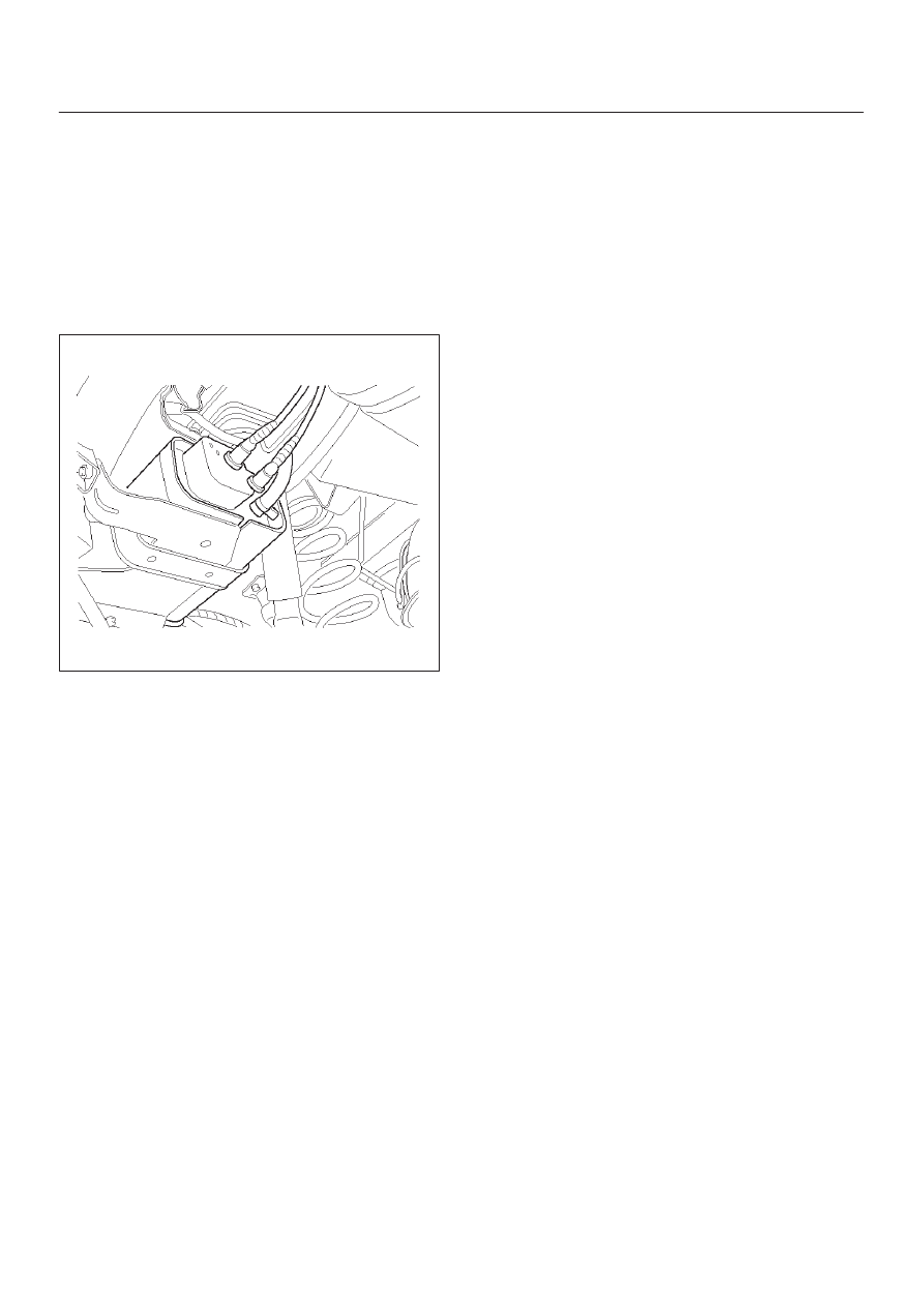
EVAP Canister. Mounted on a bracket ahead of the
fuel tank, the canister stores fuel vapors until the PCM
determines that engine conditions are right for them
to be remove and burned.
D
Fuel Tank. The tank has a built-in air space designed
for the collection of gasoline fumes.
014RW145
D
Vacuum Source. The vacuum source is split between
two ports, one on either side of the throttle body.
D
Fuel Cap. The fuel cap is designed to be an integral
part of the EVAP system.
System Fault Detection
The EVAP leak detection strategy is based on applying
vacuum to the EVAP system and monitoring vacuum
decay. The PCM monitors vacuum level via the fuel tank
pressure sensor. At an appropriate time, the EVAP purge
solenoid and the EVAP vent solenoid are turned “ON,”
allowing the engine vacuum to draw a small vacuum on
the entire evaporative emission system.
After the desired vacuum level has been achieved, the
EVAP purge solenoid is turned “OFF,” sealing the system.
A leak is detected by monitoring for a decrease in vacuum
level over a given time period, all other variables
remaining constant. A small leak in the system will cause
DTC P0442 to be set.
If the desired vacuum level cannot be achieved in the test
described above, a large leak or a faulty EVAP purge
solenoid is indicated.
Leaks can be caused by the following conditions:
D
Disconnected or faulty fuel tank pressure sensor
D
Missing or faulty fuel cap
D
Disconnected, damaged, pinched, or blocked EVAP
purge line
D
Disconnected or damaged EVAP vent hose
D
Disconnected, damaged, pinched, or blocked fuel
tank vapor line
D
Disconnected or faulty EVAP purge solenoid
D
Disconnected or faulty EVAP vent solenoid
D
Open ignition feed circuit to the EVAP vent or purge
solenoid
D
Damaged EVAP canister
D
Leaking fuel sender assembly O-ring
D
Leaking fuel tank or fuel filler neck
A restricted or blocked EVAP vent path is detected by
drawing vacuum into the EVAP system, turning “OFF” the
EVAP vent solenoid and the EVAP purge solenoid (EVAP
vent solenoid “OPEN,” EVAP purge Pulse Width
Modulate (PWM) “0%”) and monitoring the fuel tank
vacuum sensor input. With the EVAP vent solenoid open,
any vacuum in the system should decrease quickly
unless the vent path is blocked. A blockage like this will
set DTC P0446 and can be caused by the following
conditions:
D
Faulty EVAP vent solenoid (stuck closed)
D
Plugged, kinked or pinched vent hose
D
Shorted EVAP vent solenoid driver circuit
D
Plugged EVAP canister
The PCM supplies a ground to energize the purge
solenoid (purge “ON”). The EVAP purge control is PWM,
or turned “ON” and “OFF,” several times a second. The
duty cycle (pulse width) is determined by engine
operating conditions including load, throttle position,
coolant temperature and ambient temperature. The duty
cycle is calculated by the PCM and the output is
commanded when the appropriate conditions have been
met.
The system checks for conditions that cause the EVAP
system to purge continuously by commanding the EVAP
vent solenoid “ON” and the EVAP purge solenoid “OFF”
(EVAP vent solenoid “CLOSED,” EVAP purge PWM
“0%”). If fuel tank vacuum level increases during the test,
a continuous purge flow condition is indicated, which will
set a DTC P1441. This can be cause by the following
conditions:
D
EVAP purge solenoid leaking
D
EVAP purge and engine vacuum lines switched at the
EVAP purge solenoid
D
EVAP purge solenoid driver circuit grounded
General Description (Exhaust Gas
Recirculation (EGR) System)
EGR Purpose
The exhaust gas recirculation (EGR) system is use to
reduce emission levels of oxides of nitrogen (NOx). NOx
emission levels are caused by a high combustion
temperature. The EGR system lowers the NOx emission
levels by decreasing the combustion temperature.