Isuzu Amigo / Axiom / Trooper / Rodeo / VehiCross. Manual - part 882


  Index      Isuzu     Isuzu Amigo / Axiom / Trooper / Rodeo / VehiCross - service repair manual 1999-2002 year


Search            


Content   ..  880  881  882  883   ..


Isuzu Amigo / Axiom / Trooper / Rodeo / VehiCross. Manual - part 882


6E–552

TROOPER 6VE1 3.5L ENGINE DRIVEABILITY AND EMISSIONS

Metri-Pack

Tools Required

J 35689 Terminal Remover
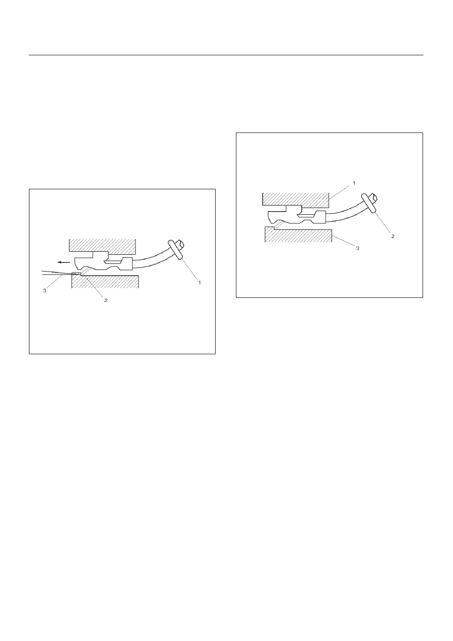
Removal Procedure

Some connectors use terminals called Metri-Pack Series
150.  These may be used at the engine coolant
temperature (ECT) sensor.

1. Slide the seal (1) back on the wire.
2. Insert the J 35689 tool or equivalent (3) in order to

release the terminal locking tang (2).

060

3. Push the wire and the terminal out through the

connector.  If you reuse the terminal, reshape the
locking tang.

Installation Procedure

Metri-Pack terminals are also referred to as “pull-to-seat”
terminals.

1. In order to install a terminal on a wire, the wire must be

inserted through the seal (2) and through the
connector (3).

2. The terminal (1) is then crimped onto the wire.

061

3. Then the terminal is pulled back into the connector to

seat it in place.

6E–553

TROOPER 6VE1 3.5L ENGINE DRIVEABILITY AND EMISSIONS

General Description (PCM and
Sensors)

58X Reference PCM Input

The powertrain control module (PCM) uses this signal
from the crankshaft position (CKP) sensor to calculate
engine RPM and crankshaft position at all engine speeds.
The PCM also uses the pulses on this circuit to initiate
injector pulses.  If the PCM receives no pulses on this
circuit, DTC P0337 will set.  The engine will not start and
run without using the 58X reference signal.

A/C Request Signal

This signal tells the PCM when the A/C mode is selected
at the A/C control head.  The PCM uses this to adjust the
idle speed before turning “ON” the A/C clutch.  The A/C
compressor will be inoperative if this signal is not
available to the PCM.
Refer to 

A/C Clutch Circuit Diagnosis section for A/C

wiring diagrams and diagnosis for the A/C electrical
system.

Crankshaft Position (CKP) Sensor

The crankshaft position (CKP) sensor provides a signal
used by the powertrain control module (PCM) to calculate
the ignition sequence.  The CKP sensor initiates the 58X
reference pulses which the PCM uses to calculate RPM
and crankshaft position.
Refer to 

Electronic Ignition System section for additional

information.

0013

Engine Coolant Temperature (ECT) Sensor

The engine coolant temperature (ECT) sensor is a
thermistor (a resistor which changes value based on
temperature) mounted in the engine coolant stream.  Low
coolant temperature produces a high resistance of
100,000 ohms at –40

°

C (–40

°

F).  High temperature

causes a low resistance of 70 ohms at 130

°

C (266

°

F).

The PCM supplies a 5-volt signal to the ECT sensor
through  resistors in the PCM and measures the voltage.
The signal voltage will be high when the engine is cold and
low when the engine is hot.  By measuring the voltage, the

PCM calculates the engine coolant temperature.  Engine
coolant temperature affects most of the systems that the
PCM controls.
The Tech 2 displays engine coolant temperature in
degrees.  After engine start-up, the temperature should
rise steadily to about 85

°

C (185

°

F).  It then stabilizes

when the thermostat opens.  If the engine has not been
run for several hours (overnight), the engine coolant
temperature and intake air temperature displays should
be close to each other.  A hard fault in the engine coolant
sensor circuit will set DTC P0177 or DTC P0118.  An
intermittent fault will set a DTC P1114 or P1115.

0016

Electrically Erasable Programmable Read
Only Memory (EEPROM)

The electrically erasable programmable read only
memory (EEPROM) is a permanent memory chip that is
physically soldered within the PCM.  The EEPROM
contains the program and the calibration information that
the PCM needs to control powertrain operation.
Unlike the PROM used in past applications, the EEPROM
is not replaceable.  If the PCM is replaced, the new PCM
will need to be programmed.  Equipment containing the
correct program and calibration for the vehicle is required
to program the PCM.

Fuel Control Heated Oxygen Sensors

The fuel control heated oxygen sensors (Bank 1 HO2S 1
and Bank 2 HO2S 1) are mounted in the exhaust stream
where they can monitor the oxygen content of the exhaust
gas.  The oxygen present in the exhaust gas reacts with
the sensor to produce a voltage output.  This voltage
should constantly fluctuate from approximately 100 mV to
900 mV.  The heated oxygen sensor voltage can be
monitored with a Tech 2.  By monitoring the voltage output
of the oxygen sensor, the PCM calculates the pulse width
command for the injectors to produce the proper
combustion chamber mixture.

D

Low HO2S voltage is a lean mixture which will result in
a rich command to compensate.

D

High HO2S voltage is a rich mixture which will result in
a lean command to compensate.

6E–554

TROOPER 6VE1 3.5L ENGINE DRIVEABILITY AND EMISSIONS

An open Bank 1 HO2S 1 signal circuit will set a DTC
P0134 and the Tech 2 will display a constant voltage
between 400-500 mV.  A constant voltage below 300 mV
in the sensor circuit (circuit grounded) will set DTC
P0131.  A constant voltage above 800 mV in the circuit will
set DTC P0132.  Faults in the Bank 2 HO2S 1 signal
circuit will cause DTC 0154 (open circuit), DTC P0151
(grounded circuit), or DTC P0152 (signal voltage high) to
set.  A fault in the Bank 1 HO2S 1 heater circuit will cause
DTC P0135 to set.  A fault in the Bank 2 HO2S 1 heater
circuit will cause DTC P0155 to set.  The PCM can also
detect HO2S response problems.  If the response time of
an HO2S is determined to be too slow, the PCM will store
a DTC that indicates degraded HO2S performance.

060RY00127

Catalyst Monitor Heated Oxygen Sensors 

Three-way catalytic converters are used to control
emissions of hydrocarbons (HC), carbon monoxide (CO),
and oxides of nitrogen (NOx).  The catalyst within the
converters promotes a chemical reaction.  This reaction
oxidizes the HC and CO present in the exhaust gas and
converts them into harmless water vapor and carbon
dioxide.  The catalyst also reduces NOx by converting it to
nitrogen.  The PCM can monitor this process using the
Bank 1 HO2S 2 and the Bank 2 HO2S 2 heated oxygen
sensors.  The Bank 1 HO2S 1 and the Bank 2 HO2S 1
sensors produce an output signal which indicates the
amount of oxygen present in the exhaust gas entering the
three-way catalytic converter.   The Bank 1 HO2S 2 and
the Bank 2 HO2S 2 sensors produce an output signal
which indicates the oxygen storage capacity of the
catalyst.  This indicates the catalyst’s ability to efficiently
convert exhaust gases.  If the catalyst is operating
efficiently,  the Bank 1 HO2S 1 and the Bank 2 HO2S 1
signals will be more active than the signals produced by
the Bank 1 HO2S 2 and the Bank 2 HO2S 2 sensors.
The catalyst monitor sensors operate the same as the
fuel control sensors.  The Bank 1 HO2S 2 and the Bank 2
HO2S 2 sensors’ main function is catalyst monitoring, but
they also have a limited role in fuel control.  If a sensor
output indicates a voltage either above or below the 450
mV bias voltage for an extended period of time, the PCM

will make a slight adjustment to fuel trim to ensure that
fuel delivery is correct for catalyst monitoring.
A problem with the Bank 1 HO2S 2 signal circuit will set
DTC P0137, P0138, or P0140, depending on the specific
condition.  A problem with the Bank 2 HO2S 2 signal
circuit will set DTC P0157, P0158, or P0160, depending
on the specific condition.  A fault in the heated oxygen
sensor heater element or its ignition feed or ground will
result in lower sensor response.  This may cause
incorrect catalyst monitor diagnostic results.

TS24067

TS23365A

Legend

(1) Bank 1 Sensor 1 (Fuel Control)
(2) Catalytic Converter
(3) Bank 1 Sensor 2 (Catalyst Monitor)
(4) Bank 2 Sensor 1 (Fuel Control)
(5) Bank 2 Sensor 2 (Catalyst Monitor)

Intake Air Temperature (IAT) Sensor

The intake air temperature (IAT) sensor is a thermistor
which changes its resistance based on the temperature of
air entering the engine.  Low temperature produces a high

6E–555

TROOPER 6VE1 3.5L ENGINE DRIVEABILITY AND EMISSIONS

resistance of 100,000 ohms at –40

°

C (–40

°

F).  High

temperature causes low resistance of 70 ohms at 130

°

C

(266

°

F) .  The PCM supplies a 5-volt signal to the sensor

through a resistor in the PCM and monitors the signal
voltage.  The voltage will be high when the incoming air is
cold.  The voltage will be low when the incoming air is hot.
By measuring the voltage, the PCM calculates the
incoming air temperature.  The IAT sensor signal is used
to adjust spark timing according to the incoming air
density.
The Tech 2 displays the temperature of the air entering
the engine.  The temperature should read close to the
ambient air temperature when the engine is cold and rise
as underhood temperature increases.  If the engine has
not been run for several hours (overnight), the IAT sensor
temperature and engine coolant temperature should read
close to each other.  A fault in the IAT sensor circuit will set
DTC P0112 or DTC P0113.

Linear Exhaust Gas Recirculation (EGR)
Control

The PCM monitors the exhaust gas recirculation (EGR)
actual position and adjusts the pintle position accordingly.
The PCM uses information from the following sensors to
control the pintle position:

D

Engine coolant temperature (ECT) sensor.

D

Throttle position (TP) sensor.

D

Mass air flow (MAF) sensor.

Mass Air Flow (MAF) Sensor

The mass air flow (MAF) sensor measures the difference
between the volume and the quantity of air that enters the
engine.  “Volume” means the size of the space to be filled.
“Quantity” means the number of air molecules that will fit
into the space.  This information is important to the PCM
because heavier, denser air will hold more fuel than
lighter, thinner air.  The PCM adjusts the air/fuel ratio as
needed depending on the MAF value.  The Tech 2 reads
the MAF value and displays it in terms of grams per
second (gm/s).  At idle, the Tech 2 should read between
4-7 gm/s on a fully warmed up engine.  Values should
change quickly on acceleration.  Values should remain
stable at any given RPM.  A failure in the MAF sensor or
circuit will set DTC P0101, DTC P0102, or DTC P0103.

0007

Manifold Absolute Pressure (MAP) Sensor

The manifold absolute pressure (MAP) sensor responds
to changes in intake manifold pressure (vacuum).  The
MAP sensor signal voltage to the PCM varies from below
2 volts at idle (high vacuum) to above 4 volts with the
ignition ON, engine not running or at wide-open throttle
(low vacuum).
The MAP sensor is used to determine the following:

D

Manifold pressure changes while the linear EGR flow
test diagnostic is being run.  Refer to 

DTC P0401.

D

Barometric pressure (BARO).

If the PCM detects a voltage that is lower than the
possible range of the MAP sensor, DTC P0107 will be set.
A signal voltage higher than the possible range of the
sensor will set DTC P0108.  An intermittent low or high
voltage will set DTC P1107, respectively.  The PCM can
detect a shifted MAP sensor.  The PCM compares the
MAP sensor signal to a calculated MAP based on throttle
position and various engine load factors.  If the PCM
detects a MAP signal that varies excessively above or
below the calculated value, DTC P0106 will set.

055RW004


Content   ..  880  881  882  883   ..