Isuzu Amigo / Axiom / Trooper / Rodeo / VehiCross. Manual - part 848


  Index      Isuzu     Isuzu Amigo / Axiom / Trooper / Rodeo / VehiCross - service repair manual 1999-2002 year


Search            


Content   ..  846  847  848  849   ..


Isuzu Amigo / Axiom / Trooper / Rodeo / VehiCross. Manual - part 848


6E–416

TROOPER 6VE1 3.5L ENGINE DRIVEABILITY AND EMISSIONS

Diagnosis Truble Code(DTC) 

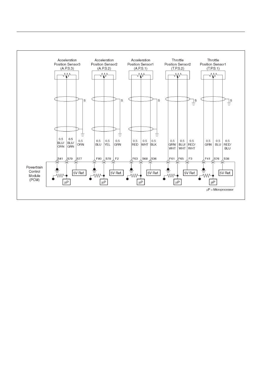
P1221 TPS1 – TPS2 correlation(Circuit Performance)

D06RY00157

Circuit Description

D

The powertrain control module (PCM) controls engine
speed by adjusting the position of the throttle control
valve (DC motor). The throttle motor is a DC motor
driven by one coil. The PCM applies current to DC
motor coil in steps (%) to adjustment the valve into a
passage in the throttle body to air flow.
This method allows highly accurate control of engine
speed and quick response to changes in engine
load.

D

The acceleration position (AP) sensor circuit provides
a voltage signal relative to acceleration pedal angle.
The acceleration pedal angle (AP1) will vary about
13% at idle position to about 87% at open
throttle(WOT).

APS signal is used to determine which DC will
adjusting throttle position.

After the APS signal has been processed by the
PCM, it will command DC motor to allow a move of
throttle position.

D

Acceleration pedal – Check for objects blocking the AP
sensor or pedal arm with spring, and excessive
deposits in the acceleration pedal arm and on the
acceleration pedal.

Diagnostic Aids

D

An intermittent may be caused by a poor connection,
rubbed–through wire insulation or a wire broken inside
the insulation. Check for poor connections or a
damaged harness. Inspect the PCM harness and
connector for improper mating, broken locks,
improperly formed or damaged terminals, poor
terminal-to-wire connection, and damaged harness.

D

Throttle body – Check for objects blocking the DC
motor or throttle bore, excessive deposits in the ETC
passage and on the valve spring, and excessive
deposits in the throttle bore and on the throttle valve
plate.

6E–417

TROOPER 6VE1 3.5L ENGINE DRIVEABILITY AND EMISSIONS

 Diagnosis Truble Code(DTC) 

P1221 TPS1 – TPS2 correlation(Circuit Perfoemance)


Step

Action

Value(s)

Yes

No

1

Was the “On-Board (OBD) System Check”performed?

Go to 

Step 2

Go to 

OBD

System

Check

2

Was the “Electric Throttle Control (ETC) System
Check” performed?

Go to 

Step 3

Go to 

ETC

System

Check

3

Following below the DTCs stored: P1120,P1220

Do any of the above require a repair?

Go to

applicable
DTC table

Go to 

Step 4

4

1. Warming up the engine until the ECT rise at 80

°

C

2. Ignition “OFF”.
3. Ignition “ON” but not engine run.
4. Observe the TP angle reading on the Tech 2 while

alowly opening the throttle.

NOTE: The value check of TPS must be performed in
less than 15 seconds.

Does the TP angle increase steadily and evenly from
the closed throttle value to the wide open throttle
value?

Closed

throttle
TPS1=
6

12%

TPS2=

88

94% Wide

open throttle

TPS1=

79

83%

TPS2=

19

23%

Go to 

Step 5

Go to 

Step 6

5

Was the DTC P1221 stored?

Go to 

Step 9

Check the

procedure.

Refer to

Diagnostic

Aids

6

1. Check the following items;

D

TPS1 and TPS2 signal curcuit for a short to
boltag or GND.

D

TPS1 and TPS2 sensor ground curcuit for high
resistance between the PCM and TP sensors.

D

TPS1 and TPS2 5 volt reference curcuit for
high risistance between the PCM and TP
sensors.

2. If aproblem found, repair wiring harness as

necessary.

Was a problem found?

Verify repair

Go to 

Step 7

7

1. Re–observe the TP angle reading on the Tech 2

while slowly operating the acceleration pedal.

Does the TP angle increase steadily and eventry from
the closed throttle value to the wide open throttle
value?

Closed

throttle
TPS1=
6

12%

TPS2=

88

94% Wide

open throttle

TPS1=

79

83%

TPS2=

19

23%

Verify repair

Go to 

Step 8

6E–418

TROOPER 6VE1 3.5L ENGINE DRIVEABILITY AND EMISSIONS

 Diagnosis Truble Code(DTC) 

P1221 TPS1 – TPS2 correlation(Circuit Perfoemance)

  (Cont'd)

Step

No

Yes

Value(s)

Action

8

1. Replace the TP sensor.

Was a problem corrected?

Verify repair

Go to 

Step 9

9

Replace the PCM.

IMPORTANT: The replacement PCM must be
programmed.

Refer to ON–Vehicle Service in Power Control Module
and Sensors for procedures.

And also refer to latest Service Bulletin. Check to see
if the latest software is released or not.

And then Down Load the LATEST PROGRAMMED
SOFTWARE to the replacement PCM.

Is the adtion complete?

Verify repair

6E–419

TROOPER 6VE1 3.5L ENGINE DRIVEABILITY AND EMISSIONS

Diagnostic Trouble Code (DTC) P1271 APS 1– 2 Correlation Error

D06RY00075

Circuit Description

D

The acceleration position (AP) sensor circuit provides
a voltage signal relative to acceleration pedal angle.
The acceleration pedal angle (AP1) will vary about
13% at idle position to about 87% at wide open
throttle(WOT).

This code detects a correlation error between APS1
and APS2.

Conditions for setting the DTC

D

The Ignition is “ON”.

D

The acceleration pedal angle difference is less than 4.5
% between ASP1 and APS2 for 50 counts within 50
test samples (15.6 m sec).

Action Taken When the DTC Sets

D

The PCM will store condition which were present when
the DTC was set as Freeze Frame and in the Failure
Records data.

Conditions for Clearing the MIL/DTC

D

The PCM will turn the MIL “OFF” on the third
consecutive trip cycle during which the diagnostic has
been run and the fault condition is no longer present.

D

A history DTC P1271 will clear after 40 consecutive trip
cycle during which the warm up cycles have occurred
without a fault.

D

DTC P1271 can be cleared using the Tech 2 “Clear
Info” function or by disconnecting the PCM battery
feed.

Diagnostic Aids

An intermittent may be caused by the following:

D

Poor connectons.

D

Mis routed harness.

D

Rubbed through wire insulation.

D

Broken wire inside the insulation.

Check for the following conditions:

D

Poor connection at PCM-Inspect harness connectors
for backed out terminals, improper mating, broken
locks, improperly formed or damaged terminals, and
poor terminal to wire connection.

D

Damaged harness-Inspect the wiring harness for
damage. If the harness appears to be OK, observe the
APP sensor 1, APP sensor 2 display on the Tech 2
while moving connectors and wiring harnesses related
to the sensor.
A change in the display will indicate the location of
the fault. If DTC P1271 cannot be duplicated,the
information included in the Faillure Records data can
be useful in determined vehicle mileage since the
DTC was last set.

If it is determined that the DTC occurs intermittently,
performing the DTC P1271 Diagnostic Chart may
isolate the cause of the fault.


Content   ..  846  847  848  849   ..