Isuzu Amigo / Axiom / Trooper / Rodeo / VehiCross. Manual - part 837
6E–372
TROOPER 6VE1 3.5L ENGINE DRIVEABILITY AND EMISSIONS
Diagnostic Trouble Code (DTC)
P1107 MAP Circuit Intermittent Low Voltage
D06R200048
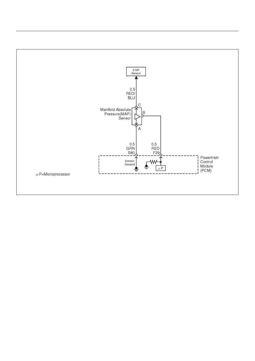
Circuit Description
The manifold absolute pressure (MAP) sensor responds
to changes in intake manifold pressure (vacuum). The
MAP sensor signal voltage to the powertrain control
module (PCM) varies from below 2 volts at idle (high
vacuum) to above 4 volts with the ignition “ON”, engine
not running or at wide-open throttle (low vacuum).
The MAP sensor is used to determine manifold pressure
changes while the linear EGR flow test diagnostic is being
run (refer to
DTC P0401), to determine engine vacuum
level for some other diagnostics and to determine
barometric pressure (BARO). The PCM compares the
MAP sensor signal to a calculated MAP based on throttle
position and various engine load factors. If the PCM
detects a MAP signal that is intermittently below the
calculated value, DTC P1107 will be set.
Conditions for Setting the DTC
D
No TP sensor DTCs are present.
D
Engine is running.
D
Ignition voltage is more than 11 volts.
D
Throttle angle is above 1% if engine speed is less than
1000 RPM.
D
Throttle angle is above 3% if engine speed is above
1000 RPM.
D
The MAP sensor indicates an intermittent manifold
absolute pressure below 11 kPa for a total of
approximately 5 seconds over a 16-second period of
time.
Action Taken When the DTC Sets
D
The PCM will not illuminate the malfunction indicator
lamp (MIL).
D
The PCM will store conditions which were present
when the DTC was set as Failure Records data only.
This information will not be stored as Freeze Frame
data.
Conditions for Clearing the MIL/DTC
D
A history DTC P1107 will Clear after 40 consecutive
warm-up cycles have occurred without a fault.
D
DTC P1107 can be cleared by using the Tech 2 “Clear
Info” function or by disconnecting the PCM battery
feed.
Diagnostic Aids
Check for the following conditions:
D
Poor connection at PCM – Inspect harness connectors
for backed-out terminals, improper mating, broken
locks, improperly formed or damaged terminals, and
poor terminal-to-wire connection.
D
The MAP Sensor shares a 5 Volt reference with the
EGR Valve. If these codes are also set, it could indicate
a problem with the 5 Volt reference circuit or
components itself.
D
The MAP Sensor share a ground with the EGR Valve
and the IAT Sensor.