Isuzu Amigo / Axiom / Trooper / Rodeo / VehiCross. Manual - part 743


  Index      Isuzu     Isuzu Amigo / Axiom / Trooper / Rodeo / VehiCross - service repair manual 1999-2002 year


Search            


Content   ..  741  742  743  744   ..


Isuzu Amigo / Axiom / Trooper / Rodeo / VehiCross. Manual - part 743


6D3–22 STARTING AND CHARGING SYSTEM

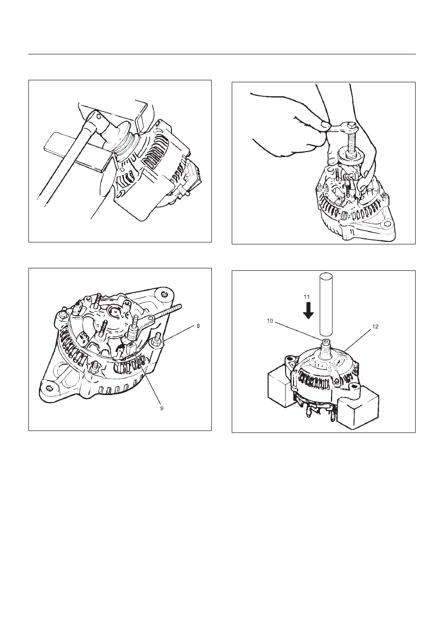
6. Secure the pulley directly in the vise between two

copper plates, and remove the nut and pulley.

066RS010

7. Remove four nuts(8) that secure the front cover

assembly and rear end cover, and an insulator(9).

066RW005

8. Use the puller to remove the rear end cover.
9. Rotor assembly

066RS012

10. Pull the rotor assembly(10) off the front cover

assembly(12) using a bench press(11).

066RW006

6D3–23

STARTING AND CHARGING SYSTEM

Inspection and Repair

Repair or replace necessary parts if extreme wear or
damage is found during inspection.

Rotor Assembly

1. Check the rotor slip ring surfaces for contamination

and roughness. If rough, polish with #500—600
sandpaper.

066RS014

2. Measure the slip ring diameter, and replace if it

exceeds the limit.

066RS015

3. Check resistance between slip rings, and replace if

there is no continuity.

066RS016

4. Check for continuity between slip ring and rotor core.

In case of continuity, replace the rotor assembly.

066RS017

6D3–24 STARTING AND CHARGING SYSTEM

Stator Coil

1. Measure resistance between respective phases.
2. Measure insulation resistance between stator coil

and core with a mega–ohmmeter.
If less than standard, replace the coil.

066RS018

Brush

Measure the brush length.
If more than limit, replace the brush.

Standard: 10.mm (0.4134 in)

Limit: 8.4.mm (0.3307 in)

066RS019

Rectifier Assembly

Check for continuity across “P” and “E” in the 

×

 100W

range of multimeter.

066RW002

Change polarity, and make sure that there is continuity in
one direction, and not in the reverse direction.  In case of
continuity in both directions, replace the rectifier
assembly.

IC Regulator Assembly

Check for continuity across “B” and “F” in the 

×

 100W

range of multimeter.

066RS021

6D3–25

STARTING AND CHARGING SYSTEM

Change polarity, and make sure that there is continuity in
one direction, and not in the reverse direction.  In case of
continuity in both directions, replace the IC regulator
assembly.

Reassembly

To reassemble, follow the disassembly steps in the
reverse order, noting the following points:

1. Using a press with a socket wrench attached,

reassemble rotor and rear end cover assembly in the
front cover.

066RS022

2. Install pulley on the rotor.

Secure the pulley directly in the vise between two
copper plates, and tighten nut to the specified torque.

Torque: 111 N·m (82 lb ft)

066RS010

Bench Test

Conduct a bench test of the generator.

066RS023

Preparation

Remove generator from the vehicle (see “Generator
removal”).

1. Secure generator to the bench test equipment and

connect wires.
Terminal “IG” for energization
Terminal “L” for neutral (warning lamp)
Terminal “B” for output

2. Conduct the generator characteristic test.

Characteristics of generator are shown in illustration.
Repair or replace the generator if its outputs are
abnormal.

B06RX001


Content   ..  741  742  743  744   ..