Isuzu Amigo / Axiom / Trooper / Rodeo / VehiCross. Manual - part 740


  Index      Isuzu     Isuzu Amigo / Axiom / Trooper / Rodeo / VehiCross - service repair manual 1999-2002 year


Search            


Content   ..  738  739  740  741   ..


Isuzu Amigo / Axiom / Trooper / Rodeo / VehiCross. Manual - part 740


6D3–10 STARTING AND CHARGING SYSTEM

Check for continuity between commutator and shaft.
Also, check for continuity between commutator and
armature core,armature core and shaft. Replace
commutator if there is continuity (i.e., internally
grounded).

065RS016

Measure runout of armature core and commutator with a
dial gauge.  Repair or replace, if it exceeds the limit.

Armature
Standard: 0.05 mm (0.002 in) Max.
Limit: 0.10 mm (0.004 in)
Commutator
Standard: 0.05 mm (0.002 in) Max.
Limit: 0.10 mm (0.004 in)

065RS017

Polish the commutator surface with sandpaper #500 to
#600 if it is rough.

065RW012

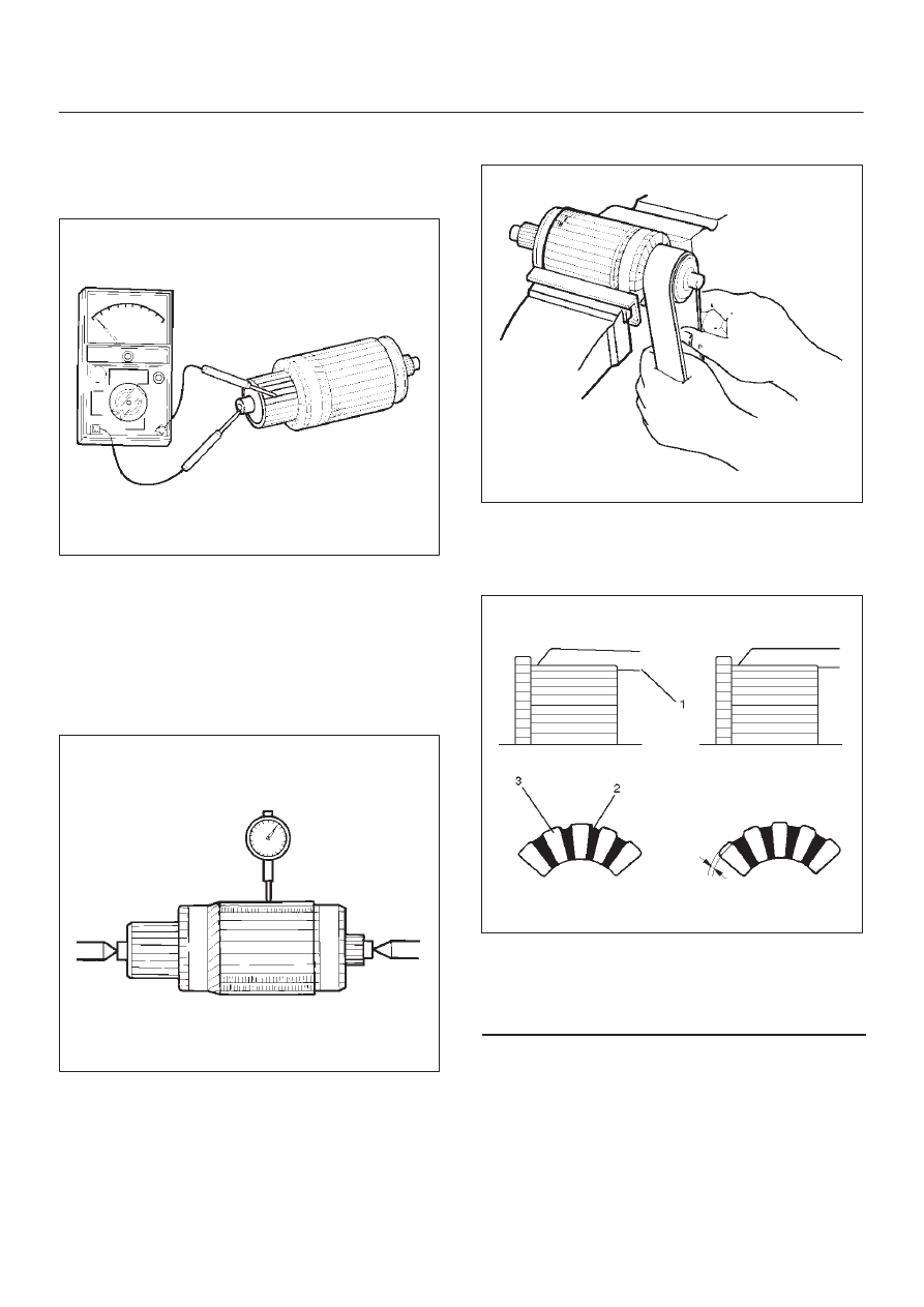
Measure the depth of insulator in commutator.  Repair, if it
is below the limit.

Standard: 0.5 mm to 0.8 mm (0.02 in to 0.03 in)
Limit: 0.2 mm (0.008 in)

065RW013

Legend

(1) Steel Saw
(2) Insulator
(3) Commutator Segments

6D3–11

STARTING AND CHARGING SYSTEM

Brush

Measure the length of brush.
Replace with a new one, if it is below the limit.

Standard: 16 mm (0.63 in)
Limit: 11 mm (0.43 in)

065RW014

Brush Holder

Check for continuity between brush holder (+) (4) and
base (–). Replace, if there is continuity (i.e., insulation is
broken).

065RW015

Magnetic Switch

Check for continuity of shunt coil between terminals S and
M.
Replace, if there is no continuity (i.e., coil is
disconnected).

065RW016

Continuity of Series Coil

Check for continuity between terminals S and M.
Replace, if there is no continuity (i.e., coil is
disconnected).

065RW017

6D3–12 STARTING AND CHARGING SYSTEM

Continuity of Contacts

With the plunger faced downward, push down the
magnetic switch. In this state, check for continuity
between terminals B and M. Replace, if there is no
continuity (i.e., contacts are faulty).

065RW018

Pinion

Check if the pinion rotates smoothly in drive direction by
hand, or if it is locked when it is rotated in reverse. If not,
replace the pinion.

065RS025

Yoke Assembly

Check a magnet inside the yoke.
Replace the yoke assembly if it is broken.

065RS026

Ball Bearing

Clamp the inner race of the ball bearing with your finger,
and check for sticking or play when rotating the outer
race.
Replace, if abnormality is found.

065RS027

6D3–13

STARTING AND CHARGING SYSTEM

Measure inner diameter of bushing in the rear cover, and
replace if it exceeds the limit.

Standard: 12.50 mm to 12.527 mm (0.492 in to
0.4932 in)
Limit: 12.60 mm (0.4961 in)

065RS028

Measure inner diameter of bushing in the center bracket
(P), and replace if it exceeds the limit.

Standard: 18.01 mm to 18.127 mm (0.7091 in to
0.7137 in)
Limit: 18.15 mm (0.7146 in)

065RS029

Reassembly

To install, follow the removal steps in the reverse order,
noting the following points:
Grease application places

D

Bushing in rear cover and center bracket

D

Gears in reduction gear

D

Shift lever operating portion

D

Sliding portion of pinion

D

Plunger sliding portion of magnetic switch

Reassembling Yoke Assembly

Before reassembly, make sure that no metallic parts
attach to the yoke assembly. Because of strong magnetic
force, hold the yoke assembly and insert it slowly into the
armature.

Torque
Torque for each part (See Torque Specifications in
this section)

Pinion Jump–out Dimension

Connect the “+” cable of battery to terminal S and the “–”
cable to terminal M. Turn the switch on, and measure
pinion travel dimension in thrust direction from the
jump–out position.
In measuring the dimension, pull the pinion out a little in
the arrow direction.

Dimension(L): 0.05 mm to 1.5 mm (0.002 in to
0.06 in)

065RS030


Content   ..  738  739  740  741   ..