Isuzu Amigo / Axiom / Trooper / Rodeo / VehiCross. Manual - part 710


  Index      Isuzu     Isuzu Amigo / Axiom / Trooper / Rodeo / VehiCross - service repair manual 1999-2002 year


Search            


Content   ..  708  709  710  711   ..


Isuzu Amigo / Axiom / Trooper / Rodeo / VehiCross. Manual - part 710


6A–21

ENGINE MECHANICAL

Cylinder Head Cover RH

Removal

1. Disconnect battery ground cable.
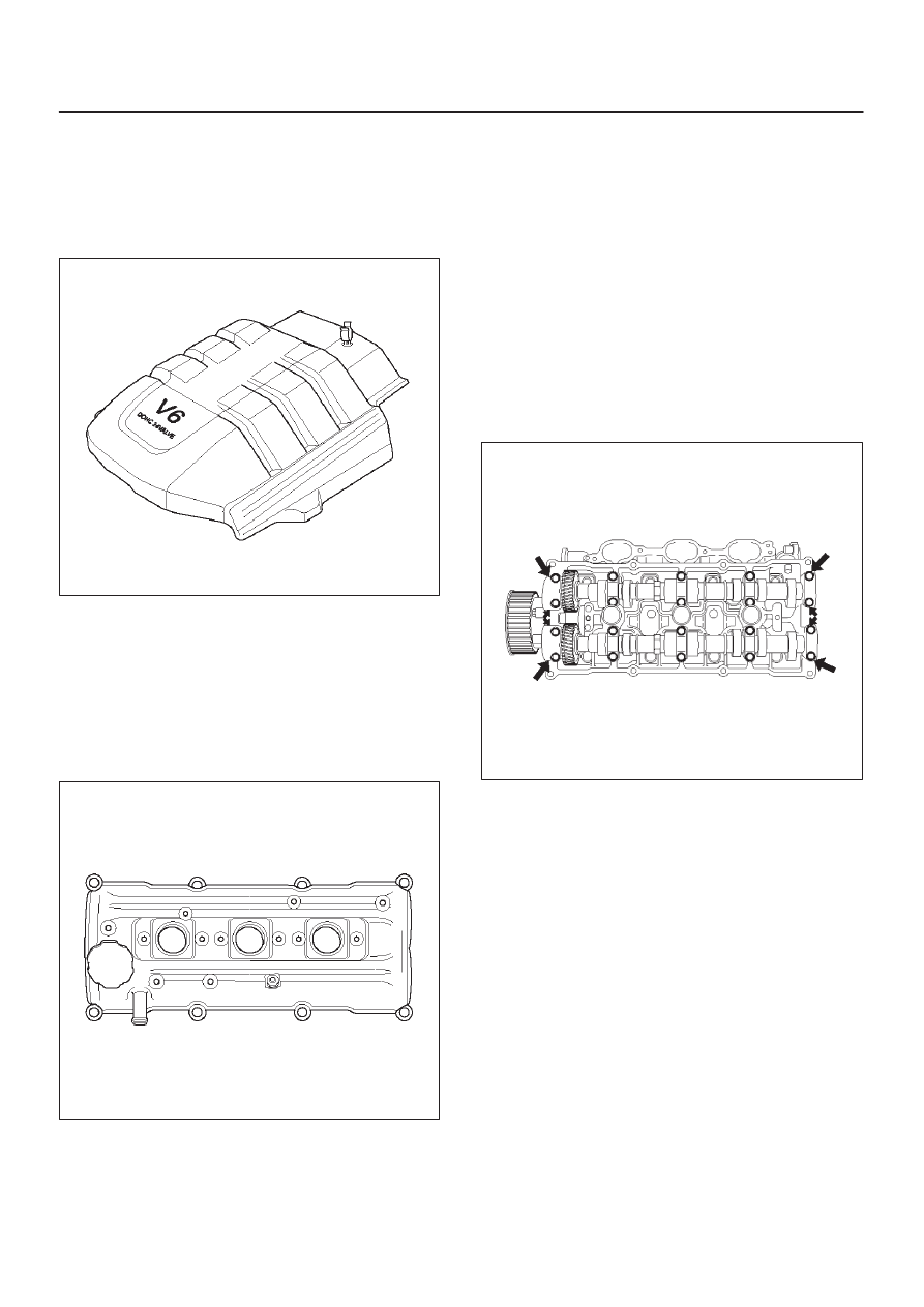
2. Remove engine cover from the dowels on the

common chamber.

F06RY001

3. Disconnect ventilation hose from cylinder head cover.
4. Disconnect three ignition coil connectors from ignition

coils and remove harness bracket bolts on cylinder
head cover then remove ignition coil fixing bolts on
ignition coils and remove ignition coils.

5. Disconnect fuel injector harness connector then

remove fuel injector harness bracket bolt.

6. Remove eight fixing bolts then the cylinder head

cover.

010RW002

Installation

1. Install cylinder head cover.

D

Clean the sealing surface of cylinder head and
cylinder head cover to remove oil and sealing
materials completely. 
Apply sealant (TB-1207B or equivalent) bead
(diameter 2-3 mm) at eight places of arched areas
of camshaft bracket on front and rear sides.

D

The cylinder head cover must be installed within 5
minutes after sealant application to prevent
premature hardening of sealant.

D

Tighten bolts to the specified torque.

Torque : 9 N·m (78 lb in)

014RW019

2. Tighten fuel injector harness bracket bolts to

specified torque then reconnect fuel injector harness
connector.

Torque : 9 N·m (78 lb ft)

3. Connect ignition coil connector and tighten ignition

coil fixing bolts to specified torque.

Torque : 4 N·m (35 lb in)

4. Connect ventilation hose to cylinder head.
5. Install engine cover mating with the dowels.

6A–22

ENGINE MECHANICAL

Common Chamber

Removal

1. Disconnect battery ground cable.
2. Remove air cleaner duct assembly.

013RY00001

Legend

(1) Positive Crankcase Ventilation Hose Connector
(2) Intake Air Temperature Sensor
(3) Air Cleaner Duct Assembly
(4) Air Flow Sensor

3. Disconnect vacuum booster hose from common

chamber.

4. Disconnect connector from manifold absolute

pressure sensor, ion sensing module, throttle position
sensor, solenoid valve, electric vacuum sensing
valve, and EGR valve.

5. Disconnect vacuum hose on canister VSV and

positive crankcase ventilation hose, fuel rail
assembly with pressure control valve bracket.

6. Remove ventilation hose from throttle valve and

intake duct and remove water hose.

7. Remove the four throttle body fixing bolts.
8. Remove exhaust gas recirculation valve assembly

fixing bolt and nut on common chamber and remove
EGR valve assembly.

9.  Remove two bolts from common chamber rear side

for remove fuel hose bracket.

10. Remove common chamber four bolts and four nuts

then remove the common chamber.

025R200001

Legend

(1) Common Chamber
(2) Throttle Valve Assembly
(3) Bolt

Installation

1. Install common chamber and tighten bolts and nuts to

the specified torque.

Torque :
Bolt : 25 N·m (18 lb ft)
Nut : 25 N·m (18 lb ft)

2. Install fuel hose bracket and tighten bolts to specified

torque.

Torque : 10 N·m (87 lb in)

3. Install exhaust gas recirculation valve assembly and

tighten bolt and nut to the specified torque.

Torque : 25 N·m (18 lb ft)

4. Install throttle body and tighten bolts to the specified

torque.

Torque : 25 N·m (18 lb ft)

5. Install ventilating hose to throttle valve and intake

duct.

6. Connect vacuum hoses on canister VSV and positive

crankcase ventilation hose. Tighten bolts for fuel rail
assembly with pressure control valve bracket.

Torque : 25 N·m (18 lb ft)

7. Connect each connector without fail.
8. Connect vacuum booster hose.

6A–23

ENGINE MECHANICAL

9. Connect the ion sensing module connectors as

shown in the illustration.

060RY00111

Legend

(1) Green Connector
(2) Blue Connector
(3) Identification Mark (6VE1 Engine Only)

10. Install air cleaner duct assembly.

013RY00001

Legend

(1) Positive Crankcase Ventilation Hose Connector
(2) Intake Air Temperature Sensor
(3) Air Cleaner Duct Assembly
(4) Mass Air Flow Sensor

6A–24

ENGINE MECHANICAL

Exhaust Manifold LH

Removal

1. Disconnect battery ground cable.
2. Remove transfer case skid plate.
3. Remove 3rd crossmember.
4. Disconnect Heated oxygen (O

2

) sensor connector.

5. Remove the three stud nuts from the front exhaust

pipe flange and two nuts from the rear exhaust pipe
flange.

035RX015

Legend

(1) O

2

 Sensors

(2) Exhaust Front Pipe LH
(3) Transfer Case Skid Plate
(4) 3rd Crossmember

6. Remove heat protector two fixing bolts then the heat

protector.

7. Remove a bolt on engine LH side for air conditioner

(A/C) compressor bracket and loosen two bolts for
A/C compressor then move A/C compressor to front
side.

8. Remove exhaust manifold eight fixing nuts and

remove exhaust manifold from the engine.

Installation

1. Install exhaust manifold and gasket and tighten

exhaust manifold fixing nuts to the specified torque
with new nuts.

Torque: 52 N·m (38 lb ft)

2. Install heat protector.
3. Install exhaust front pipe’s three stud nuts and rear

pipe’s two nuts to the specified torque.

Torque : 
Stud nuts: 67 N·m (49 lb ft)
Nuts (Exhaust front pipe LH–RH): 57 N·m (42 lb
ft)
Nuts (Exhaust front pipe –silencer): 43 N·m (32
lb ft)

4. Set A/C compressor to normal position and tighten

two bolts to the specified torque.

Torque : 40 N·m (30 lb ft)

5. Reconnect O

2

 sensor connectors.

6. Install 3rd crossmember.
7. Install transfer case skid plate.


Content   ..  708  709  710  711   ..