Isuzu Amigo / Axiom / Trooper / Rodeo / VehiCross. Manual - part 688


  Index      Isuzu     Isuzu Amigo / Axiom / Trooper / Rodeo / VehiCross - service repair manual 1999-2002 year


Search            


Content   ..  686  687  688  689   ..


Isuzu Amigo / Axiom / Trooper / Rodeo / VehiCross. Manual - part 688


5B–2

ANTI–LOCK BRAKE SYSTEM

Electronic Hydraulic Control Unit

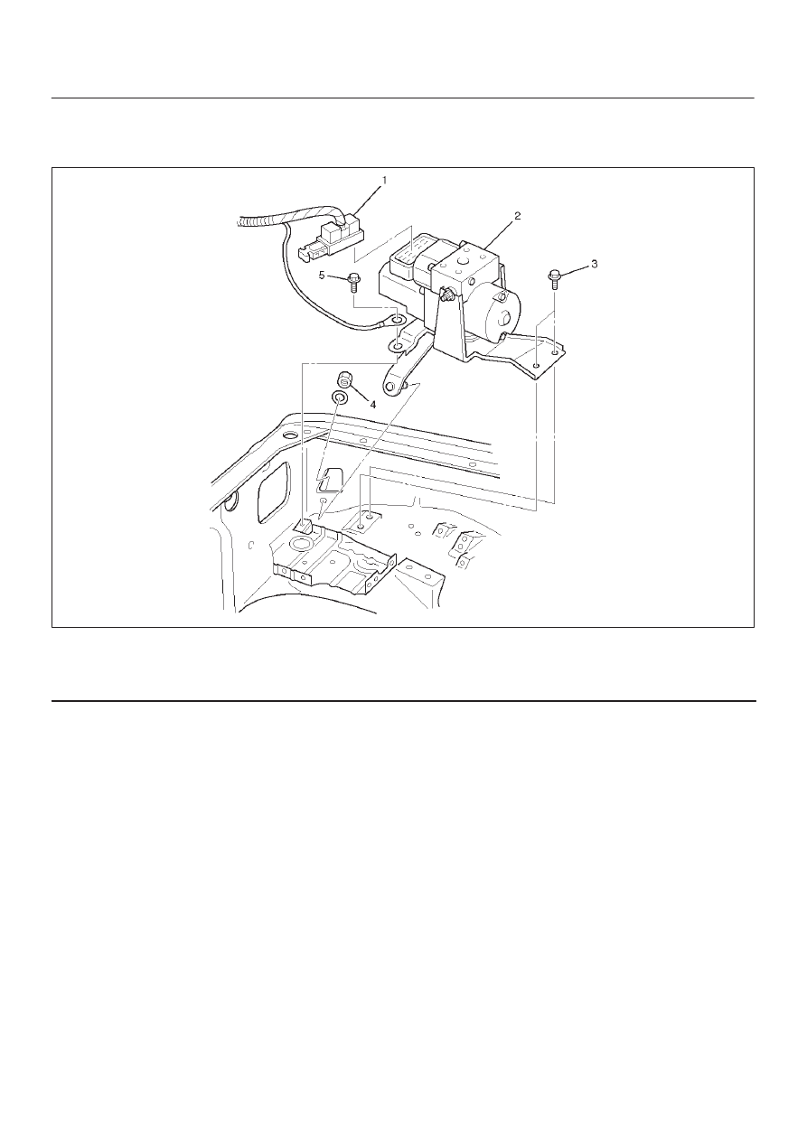
Electronic Hydraulic Control Unit and Associated Parts

350RW013

Legend

(1) Connector
(2) Hydraulic Unit ASM

(3) Bolts
(4) Nut
(5) Bolt

Removal

1. Remove battery ASM.
2. Remove harness connector.
3. Remove EHCU fixing nuts.
4. Remove brake pipes.

D

After disconnecting brake pipe, cap or tape the
openings of the brake pipe to prevent the entry of
foreign matter.

5. Remove hydraulic unit fixing nuts.

Installation

To install, follow the removal steps in the reverse order,
noting the following points:

Torque
Hydraulic unit fixing nuts : 22 N·m (16 lb ft)
Ground cable : 14 N·m (10 lb ft)
Brake pipe (joint bolts) : 16 N·m (12 lb ft)

D

After installing the hydraulic unit, bleed brakes
completely.  See Section 5A “Hydraulic Brakes”.

5B–3

ANTI–LOCK BRAKE SYSTEM

G-Sensor

Removal

350RX001

1. Remove center console.

D

Refer to Consoles in Body and Accessories
section.

2. Remove clip from G-sensor connector, then

disconnect connector.

3. Remove G-sensor assembly fixing bolt (2).
4. Remove G-sensor assembly (3).

Inspection and Repair

Refer to “Chart B-5” in this Section.

Installation

1. Install G-sensor assembly (3).

D

Care should be taken so that the G-sensor is not
installed in the wrong direction.

2. Install G-sensor assembly fixing bolt (2).

D

Tighten the fixing bolt to the specified torque.

Torque : 10 N·m (87 lb in)

3. Install G-sensor wiring connector (1).
4. Install center console.

D

Refer to Consoles in Body and Accessories
section.

5B–4

ANTI–LOCK BRAKE SYSTEM

Front Wheel Speed Sensor

Front Wheel Speed Sensor and Associated Parts

350RW012

Legend

(1) Speed Sensor Connector
(2) Sensor Cable Fixing Bolt (Upper side)

(3) Sensor Cable Fixing Bolt (Lower side)
(4) Sensor Cable Fixing Bolt (Sensor side)
(5) Speed Sensor

Removal

1. Remove speed sensor connector.
2. Remove sensor cable fixing bolt (Upper side).
3. Remove sensor cable fixing bolt (Lower side).
4. Remove the speed sensor cable fixing bolts (1) and

caliper fixing bolt (2) from caliper side speed sensor
cable bracket (3).

350RW010

5. Remove speed sensor.

5B–5

ANTI–LOCK BRAKE SYSTEM

Inspection and Repair

1. Check the speed sensor pole piece for presence of

foreign materials; remove any dirt, etc.

2. Check the pole piece for damage; replace speed

sensor if necessary.

3. Check the speed sensor cable for short or open

circuit, and replace with a new one if necessary.
To check for cable short or open, bend or stretch the
cable while checking for continuity.

4. Check the sensor ring for damage including tooth

chipping, and if damaged, replace the sensor ring
assembly.  Refer to removal of the sensor ring in
Section 4C “Front hub and disc”.

Installation

1. Install speed sensor and take care not to hit the speed

sensor pole piece during installation.

2. Install speed sensor fixing bolt and tighten the fixing

bolt to the specified torque.

Torque
Sensor side : 8 N·m (69 lb in)
Caliper side : 155 N·m (115 lb ft)

350RW011

Legend

(1) Caliper Fixing Bolt
(2) Bracket
(3) Sensor Fixing Bolt
(4) Sensor
(5) Knuckle
(6) Brake Caliper

3. Install speed sensor cable fixing bolt (Lower side) and

tighten the fixing bolt to the specified torque.

Torque : 24 N·m (18 lb ft)

4. Install speed sensor cable fixing bolt (Upper side) and

tighten the fixing bolt to the specified torque.

Torque : 6 N·m (52 lb ft)

NOTE: Confirm that a white line marked on the cable is
not twisted when connecting the speed sensor cable.

5. Install speed sensor connector.


Content   ..  686  687  688  689   ..