Isuzu Amigo / Axiom / Trooper / Rodeo / VehiCross. Manual - part 678
5A–8
BRAKE CONTROL SYSTEM
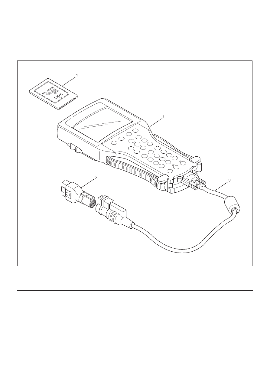
Tech 2 Scan Tool
From 98 MY, Isuzu dealer service departments are
recommended to use Tech 2. Please refer to Tech 2 scan
tool user guide.
901RW257
Legend
(1) PCMCIA Card
(2) SAE 16/19 Adaptor
(3) DLC Cable
(4) Tech–2