Isuzu Amigo / Axiom / Trooper / Rodeo / VehiCross. Manual - part 668


  Index      Isuzu     Isuzu Amigo / Axiom / Trooper / Rodeo / VehiCross - service repair manual 1999-2002 year


Search            


Content   ..  666  667  668  669   ..


Isuzu Amigo / Axiom / Trooper / Rodeo / VehiCross. Manual - part 668


TRANSFER CASE (TOD) 4D2–11

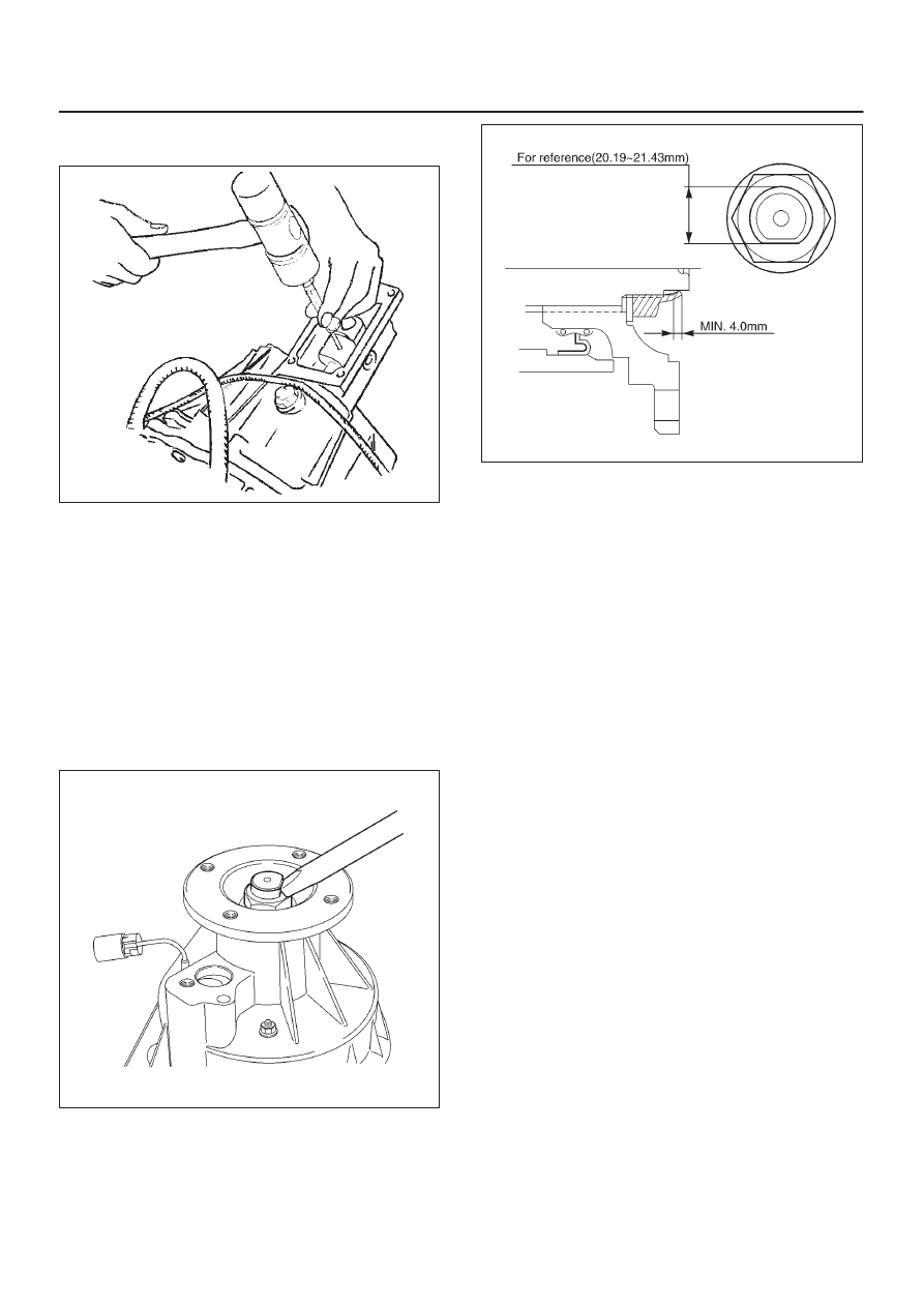
4. Mount the offset lever to the transfer shift and install

the spring pin.

261RW016

5. Attach the O-ring and washer to the companion

flange.

NOTE: Securely push the O-ring to the hollow of the
companion flange, and then attach the washer.

6. Use the flange holder J-8614-11 to tighten the flange

nut.

7. Tighten the flange nut with the specified torque.

Torque : 167 N·m (123 lb ft)

8. Securely stake the flange nut at one place so that

there is no gap between a flat poriton on the shaft and
the nut staked portion.

NOTE: Check the staked flange nut is free from cracks.

266RY00003

266R200005

9. Fix the harness with the clip.

10. Tighten the 4L and 4H switch to the specified torque.

Torque : 24 N·m (17 lb ft)

11. Fill the transfer case with ATF II or III (1.9 liters).

12. Wind the sealing tape around the filler plug thread and

tighten the plug to the specified torque.

Torque : 25 N·m (18 lb ft)

4D2–12 TRANSFER CASE (TOD)

Transfer Cover Assembly

Disassembled View

261RW007

Legend

(1) Coil Assembly
(2) Snap Ring
(3) Ball Bearing

(4) Speed Gear and Tone Wheel
(5) Ball Bearing
(6) Transfer Cover Assembly
(7) Front and Rear Speed Sensors

Disassembly

1. Using snap ring pliers, remove the snap ring.

261RW047

TRANSFER CASE (TOD) 4D2–13

2. Strike the speed gear and tone wheel with a rod or

other appropriate tool from the outside of the transfer
cover assembly, and remove the ball bearing and
speed gear and tone wheel.

NOTE: Be careful not to damage the speed gear teeth.

266RW018

3. Remove the stopper plate on the back with a

precision screwdriver or other appropriate tool
starting from the small lock of the plate.

NOTE: Be careful not to damage the stopper plate during
the work.

261RW042

4. Using a terminal pull-out tool or an equivalent tool,

push down the lock to unlatch the terminal for the coil
assembly, and pull the terminal out.

NOTE: Pay attention not to damage other terminals.

261RW032

5. Remove the fixing nuts of the coil assembly from the

outside of the transfer cover assembly.  Remove the
coil assembly from the transfer cover.

261RW030

4D2–14 TRANSFER CASE (TOD)

6. Using the bearing remover J-42805 and slide

hammer J-2619-01, remove the ball bearing for the
front output shaft.

901RW087

7. Remove the bolts and front and rear speed sensors.

NOTE: Be careful not to damage the speed sensors
during the work.

261RW033

Reassembly

1. Remove the oil seal from the transfer cover assembly.
2. Apply oil to the circumference of the new oil seal and

fill the lip with grease (Besco L2 or equivalent).

3. Using the oil seal installer J-42804, install the oil seal

to the transfer cover assembly.

261RW035

Rear Output Shaft Oil Seal

Distance between the transfer case end and oil seal.

NOTE: When installing the oil seal to the specified
dimension, be careful not to damage it.

Dimension : 9.85–10.35 mm (0.39–0.41 in)

A04RW004

4. Apply a thin coat of grease to the seal ring of each

front and rear speed sensor, and mount the sensor
carefully.

5. Tighten the bolt to the specified torque.

Torque : 5 N·m (43 lb in)

NOTE: Pay attention not to mount the front (or rear)
sensor to the rear (or front) sensor position.

6. Install the ball bearing (1) for the front output shaft as

flat as shown in the figure.

7. Mount the coil assembly and tighten the set nuts to

the specified torque.

Torque : 10 N·m (87 lb in)


Content   ..  666  667  668  669   ..