Isuzu Amigo / Axiom / Trooper / Rodeo / VehiCross. Manual - part 628


  Index      Isuzu     Isuzu Amigo / Axiom / Trooper / Rodeo / VehiCross - service repair manual 1999-2002 year


Search            


Content   ..  626  627  628  629   ..


Isuzu Amigo / Axiom / Trooper / Rodeo / VehiCross. Manual - part 628


DRIVE LINE CONTROL SYSTEM (TOD)

4B2–32

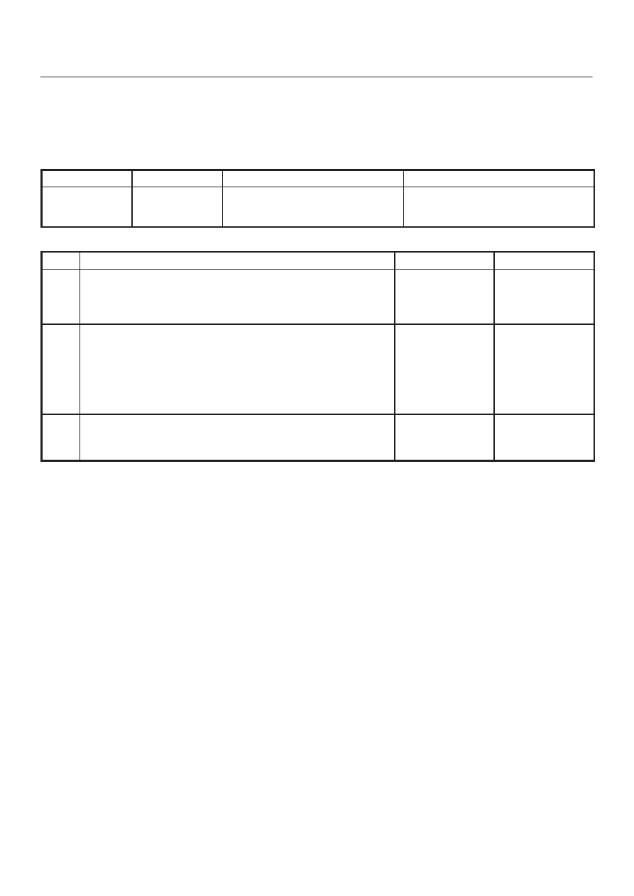
Diagnosis from Trouble Codes

D

Diagnose the based on the fault that have been saved
to the control unit according to the system
self-diagnostic function.

Check flow

Trouble code

Phenomenon

Standard

1

 23, 36,

37(P1712),

38(P1714)

The ECU has failed.

Step

Action

Yes

No

1

Turn on the starter switch.

Is the trouble reproduced?

Replace the ECU

and conduct the

test run.

Go to Step 3

Go to Step 2

2

1. Clear the trouble codes.
2. Conduct the test run.

Is the trouble reproduced during the test run?

Replace the ECU

and conduct the

test run.

Go to Step 3

The trouble is not

reproduced.

Refer to

“Troubles

intermittently

observed”.

Go to Step 3

3

1. Check that all the parts are mounted.
2. Clear the trouble codes.

Is this step complete?

Repeat the

“Diagnosis Flow”.

Return to Step 3

4B2–33

DRIVE LINE CONTROL SYSTEM (TOD)

Check flow

Trouble code

Phenomenon

Standard

2

14

(P1731)

Front speed sensor signal open or

GND short, speed sensor com

open.

0.3 > sensor voltage

NOTE: The following procedure shows the case that the
front or rear sensor common grounding line is broken.

D04RY00004

DRIVE LINE CONTROL SYSTEM (TOD)

4B2–34

Step

Action

Yes

No

1

1. Start the engine.
2. Select TOD mode.

Is there the memory except DTC 14(P1731)?

Go to Step 4

Go to Step 2

2

1. Turn off the starter switch.
2. Disconnect the ECU connector (B–48) and (B–49).

Is there the continuity between the connector (B–48) terminal 10
and 25?

Repair the circuit.

Go to Step 7

Go to Step 3

3

1. Disconnect the transfer connector (M–27).

Is there the continuity between the connector (B–48) terminal 10
and the connector (M–27) terminal 6, the connector (B–49)
terminal 12 and connector (M–27) terminal 2, and the connector
(B–49) terminal 13 and connector (M–27) terminal 10?

Replace the front

speed sensor.

Go to Step 7

Repair the circuit.

Go to Step 7

4

Is the memory DTC 24(P1733)?

Go to Step 5

Refer to other

trouble check

flow.

5

Is there the continuity between harnesses of terminal 32 and 45
(vehicle side terminal of the front and rear speed sensor)?

Go to Step 6

Repair the circuit.

Go to Step 7

6

Is there the continuity between harnesses of terminal 12 and 13
(vehicle side terminal of the speed sensor COM(–) and ref)?

Replace front and

rear speed

sensor.

Go to Step 7

Repair the circuit.

Go to Step 7

7

1. Check that all the parts are mounted.
2. Clear the trouble code.

Is the step complete?

Verify the repair.

Return to Step 7

4B2–35

DRIVE LINE CONTROL SYSTEM (TOD)

Check flow

Trouble code

Phenomenon

Standard

3

16

(P1737)

The front speed sensor no pulse.

Hi level : 4.5 

 6.0 V

Lo level : 0.7 

 2.0 V

Frequency (F) =

700 – 850 Hz (at 30 mile/h)

NOTE: Find the trouble in which the pulse corresponding
to the running speed is not input.

D04RY00004


Content   ..  626  627  628  629   ..