Isuzu Amigo / Axiom / Trooper / Rodeo / VehiCross. Manual - part 574
POWER ASSISTED SYSTEM
2A–25
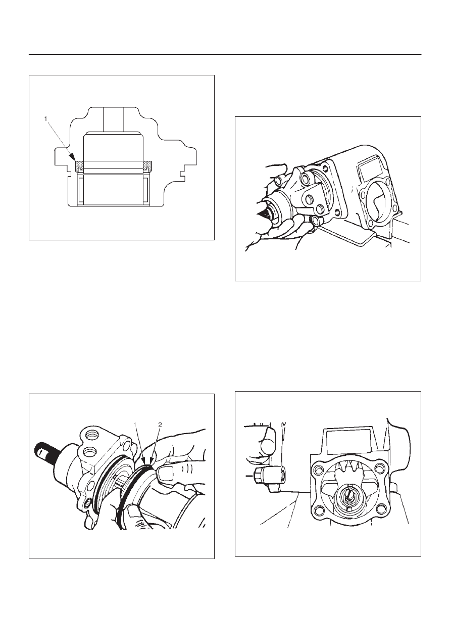
Gasket Setting
440RW002
D
Note the gasket(1) installation direction.
D
Apply a thin coat of power steering fluid to lip of each
part.
Reassembly
1. Install gear box.
2. Apply a thin coat of power steering fluid to the new
O-ring(2) and be sure to discard used part, then install
o-ring.
3. Apply a thin coat of power steering fluid to the new
seal ring(1) and be sure to discard used part, then
install seal ring.
4. Apply a thin coat of power steering fluid to the new
O-ring and be sure to discard used part, then install
o-ring.
440RS010
5. Install ball-nut and valve housing assembly.
D
Always keep the ball screw and valve housing
assembly in a horizontal position (avoid holding it
vertically), or the rack piston will fall off onto the end
of the worm, causing the rack piston to slip out of the
worm shaft and ball to fall out.
440RS005
D
Be careful not to drop the O-ring into the valve
housing.
D
Tighten the valve housing bolts to the specified
torque.
Torque: 47 N·m (35 lb ft)
6. Install sector shaft.
D
Tape the sector shaft serrations to protect the seal
ring from damage.
D
Align the center tooth of ball nut with that of the
sector shaft.
440RS004
7. Install O-ring.