Isuzu Amigo / Axiom / Trooper / Rodeo / VehiCross. Manual - part 571


  Index      Isuzu     Isuzu Amigo / Axiom / Trooper / Rodeo / VehiCross - service repair manual 1999-2002 year


Search            


Content   ..  569  570  571  572   ..


Isuzu Amigo / Axiom / Trooper / Rodeo / VehiCross. Manual - part 571


POWER ASSISTED SYSTEM

2A–13

Steering Wheel Free Play Adjustment

Inspection

430RS015

1. With the tires in the straight-ahead position, check the

amount of steering wheel play by turning the wheel in
both directions until the tires begin to move.

NOTE: The wheel free play should be checked with the
engine running.

Free play: 0 – 30 mm (0 – 1.18 in)

2. Also check the steering wheel for play and looseness

in the mount by moving it back and forth and
sideways.  When test driving, check for hard steering,
steering shimmy and tendency to pull to one side. 

Adjustment

431RS001

1. Align the front wheels properly in the straight ahead

position.

2. Loosen the lock nut on the adjusting screw of the

steering gear.

3. Turn the adjust screw clockwise to decrease free play

or counter-clockwise to increase.

4. After check of specified free play, tighten the lock nut

to specified torque.

Torque: 41 N·m (30 lb ft)

Front End Alignment Inspection and
Adjustment

General Description

“Front End Alignment” refers to the angular relationship
between the front wheels
, the front suspension attaching
parts and the ground.
Proper front end alignment must be maintained in order to
insure efficient steering, good directional stability and to
prevent abnormal tire wear.
The most important factors of front end alignment are
wheel toe-in, wheel camber and axle caster.
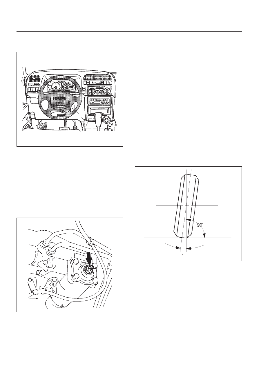
Camber:
This illustration is viewed from the front of the vehicle.

480RS004

Camber is the vertical tilting inward or outward of the front
wheels.  When the wheels tilt outward at the top, the
camber is positive (+).   When the wheels tilt inward at the
top, the camber is negative (–). The amount of tilt
measured in degrees from the vertical is called the
camber angle (1).  If camber is extreme or unequal
between the wheels, improper steering and excessive tire
wear will result.  Negative camber causes wear on the
inside of the tire, while positive camber causes wear to the
outside.

2A–14

POWER ASSISTED SYSTEM

Caster:
This illustration is viewed from the side of the vehicle.

480RS005

Caster(1) is the vertical tilting of the wheel axis either
forward or backward (when viewed from the side of the
vehicle).  A backward tilt is positive(+) and a forward tilt is
negative (–). On the short and long arm type suspension
you cannot see a caster angle without a special
instrument, but if you look straight down from the top of
the upper control arm to the ground, the ball joints do not
line up (fore and aft) when a caster angle other than 0
degree is present.  With a positive angle, the lower ball
joint would be slightly ahead (toward the front of the
vehicle) of the upper ball joint center line.

Toe-in:
This illustration is viewed from the top of the vehicle.

480RS003

Toe-in is the measured amount the front wheels are
turned in. The actual amount of toe-in is normally a
fraction of a degree.  Toe-in is measured from the center
of the tire treads or from the inside of the tires.  The
purpose of toe-in is to insure parallel rolling of the front
wheels and to offset any small deflections of the wheel
support system which occurs when the vehicle is rolling
forward.  Incorrect toe-in results in excessive toe-in and
unstable steering.  Toe-in is the last alignment to be set in
the front end alignment procedure.

Inspection

Before making any adjustments affecting caster, camber
or toe-in, the following front end inspection should be
made.

1. Inspect the tires for proper inflation pressure.  Refer to

Main Data and Specifications in Wheel and Tire
System section.

2. Make sure that the vehicle is unladen condition (With

no passenger or loading).

3. Make sure that the spare tire is installed at the normal

position.

4. Inspect the front wheel bearings for proper

adjustment.  Refer to Front Hub and Disc Overhaul in
Suspension section.

5. Inspect the ball joints, tie rod ends and relay rods.  If

excessive looseness is noted, correct before
adjusting. Refer to Steering Linkage in this section.

6. Inspect the wheels and tires for run-out.  Refer to

Wheel Replacement in Wheel and Tire System
section.

7. Inspect the trim height.  If not within specifications,

the correction must be made before adjusting caster.

8. Inspect the steering gear for looseness at the frame.
9. Inspect the shock absorbers for leaks or any

noticeable noise. Refer to Shock Absorber
Replacement
 in Suspension section.

10. Inspect the control arms or stabilizer bar attachment

for looseness.  Refer to Suspension section.

11. Inspect the front end alignment using alignment

equipment. Follow the manufacturer’s instructions.

12. Park the vehicle must be on a level surface.

POWER ASSISTED SYSTEM

2A–15

Trim Height Adjustment

Adjust the trim height(1) by means of the adjusting bolt on
the height control arms.

CAUTION: When adjusting front end alignment, be
sure to begin with trim height first, as it may change
other adjusted alignments.

450RS003

410RS001

1. Check and adjust the tire inflation pressures.
2. Park the vehicle on a level ground and move the front

of the vehicle up and down several times to settle the
suspension.

3. Make necessary adjustment with the adjusting bolt on

the height control arms.

Trim height: 129 mm (5.08 in)

Caster Adjustment

The caster angle can be adjusted by means of the caster
shims(1) installed between the chassis frame(2) and
fulcrum pins.

Caster angle: 2

°

10’ 

±

 45’

CAUTION: Left and right side must be equal within
30’.

450RS001

450RS002

NOTE: Difference of the caster shim front/rear thickness
should be 3.6 mm (0.142 in) or less. Overall thickness of
caster shim and camber shim should be 10.8 mm
(0.425 in) or less.
Tighten the fulcrum pin bolt to the specified torque.

Torque: 152 N·m (112 lb ft)

2A–16

POWER ASSISTED SYSTEM

Camber Adjustment

The camber angle can be adjusted by means of the
camber shims(2) installed in position between the chassis
frame(1) and fulcrum pins

Camber angle: 0

°


±

 30’

King pin inclination: 12

°

30’ 

±

 30’

CAUTION: Left and right side must be equal within
30’.

450RS004

450RS005

NOTE: Overall thickness of caster shim and camber
shim should be 10.8 mm (0.425 in) or less.
Tighten the fulcrum pin bolt to the specified torque.

Torque: 152 N·m (112 lb ft)

Position of shims

Front side

Rear side

Camber angle

Caster angle

When added

When removed

Decreases

Decreases

When removed

When added

Increases

Increases

Caster shim

When removed

Unchanged

Decreases

When added

Unchanged

Increases

When added

Decreases

Unchanged

Camber shim

When removed

Increases

Unchanged


Content   ..  569  570  571  572   ..