Isuzu Amigo / Axiom / Trooper / Rodeo / VehiCross. Manual - part 438
7A1–62 TRANSMISSION CONTROL SYSTEM (4L30–E)
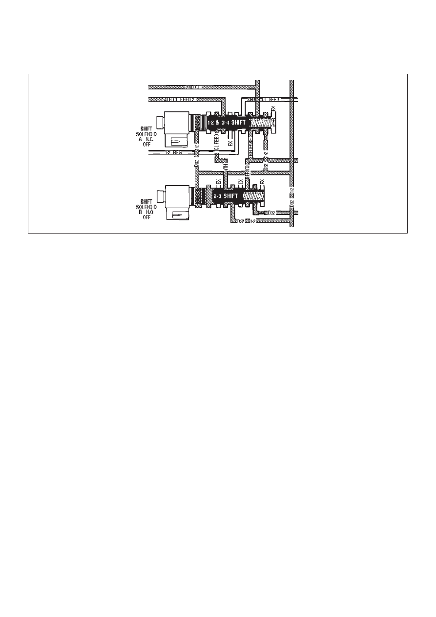
DTC P0752 Shift Solenoid A Performance (Stuck On)
D07RT011
Circuit Description
The shift solenoid A is used to control fluid flow acting on
the 1–2 and 3–4 shift valves. The solenoid is a normally
close exhaust valve that is used with the shift solenoid B
to allow four different shifting combinations.
The DTC detects when there is only a 2–2–3–3 shift
pattern depending on the state of the mechanical failure
instead of a 1–2–3–4 shift pattern. This is a type “B” DTC.
Conditions For Setting The DTC
D
No ETC DTCs.
D
No OSS DTCs P0722 or P0723.
D
No TCC solenoid DTC P0742, P1860, P1870.
D
No shift solenoid A DTC P0753.
D
No shift solenoid B DTC P0758.
D
Gear range is D4.
D
Output speed is greater than 375 rpm.
D
Transmission temperature is between 20
°
and 130
°
C
(68
°
and 266
°
F).
D
No range code P0705, P0706.
D
No torque code (to be confirmed).
D
Engine run for more 0 seconds and not influed cut-off
(to be confirmed).
All the above conditions have been met and the
combination of condition 1, 2 occur two consecutive
times.
Condition 1:
D
1st gear is commanded for
≥
1 sec
D
40
≤
Engine Torque
≤
400 N·m
D
Throttle positon
≥
10%
D
–8000
≤
TCC slip
≤
8000 rpm
D
Transmission out speed
≥
375 rpm
D
Speed ratio
≥
0.3
D
1.5
≤
Modeled Ratio
≤
2.4 for 0.687 seconds
Condition 2:
D
4th Gear is commanded for
≥
1 sec.
D
40
≤
Engine Torque
≤
400 N·m
D
Trottle position
≥
10%
D
–8000
≤
TCC slip
≤
8000 rpm
D
Speed ratio
≥
0.6
D
0.92
≤
Modeled Ratio
≤
1.5 for 7 seconds
Action Taken When the DTC Sets
D
Maximum line pressure.
D
For lamp illuminate refer to
DTC type definition (type
B).
D
Turn Force Motor OFF.
Conditions For Clearing The The MIL/DTC
D
The PCM will turn off the MIL and CHECK TRANS
Lamp after three consecutive ignition cycles without a
failure reported.
D
The DTC can be cleared from the PCM history by
using a scan tool.
D
The DTC will be cleared from history when the vehicle
has achieved 40 warmup cycles without a failure
reported.
D
The PCM will cancel the DTC default actions when
the fault no longer exists and the ignition is cycled “off”
long enough to power down the PCM.
Diagnostic Aids
D
Verify that the transmission meets the specifications
in the 4L30–E shift speed chart.
D
Other internal transmission failures may cause more
than one shift to occur.