Isuzu Amigo / Axiom / Trooper / Rodeo / VehiCross. Manual - part 394
6G–6
ENGINE LUBRICATION (6VE1 3.5L)
051RW001
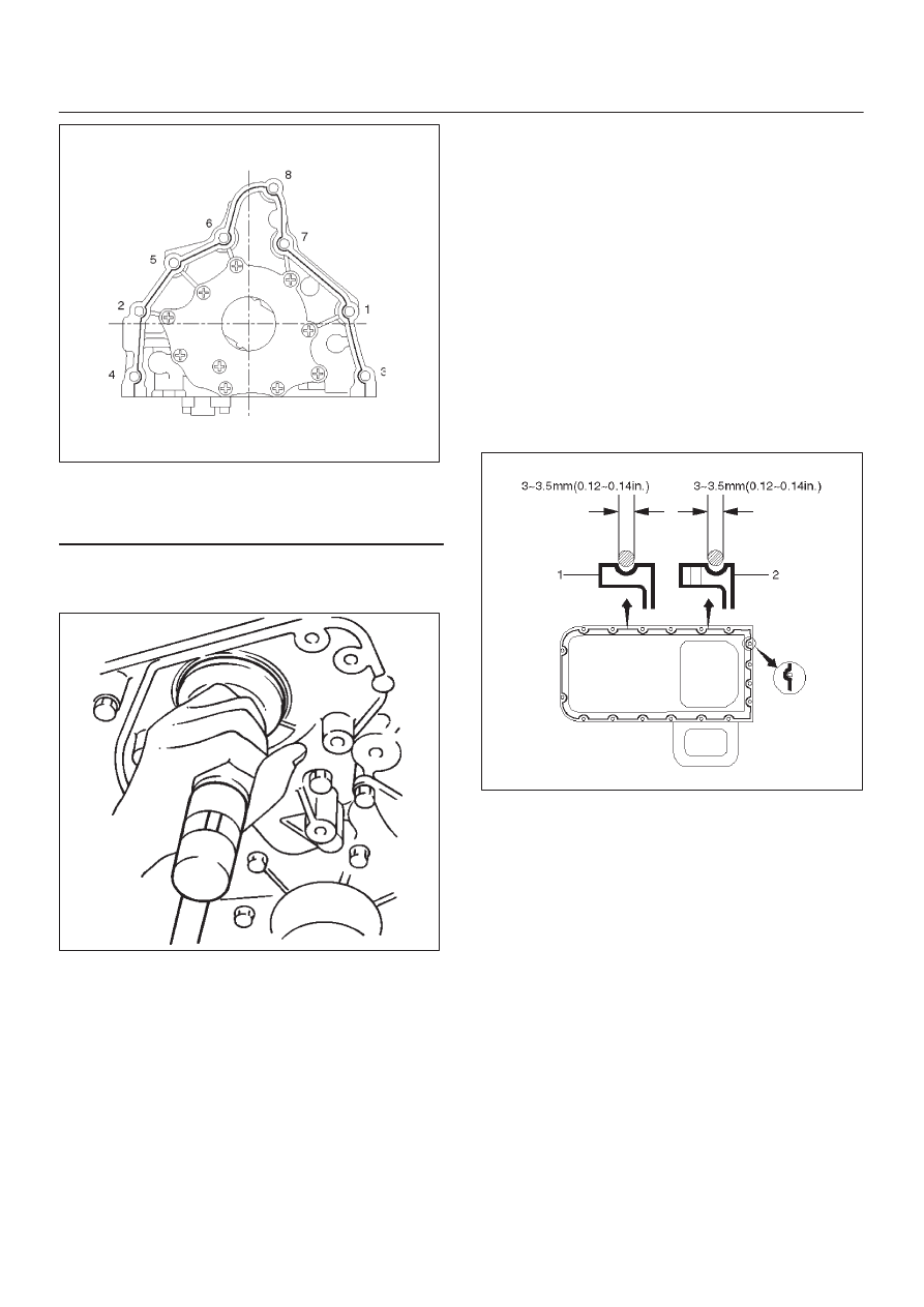
Legend
(1) Around Bolt Holes
(2) Around Dowel Pin
8. Install the new oil seal (12). Apply engine oil to the oil
seal lip before installation then use J–39202 oil seal
Installer, install oil seal.
015RS001
9. Install oil strainer (4) with O-ring (13).
Torque: 25 N·m (18 lb ft)
10. Install oil pipe (3) with O-ring (13).
Torque: 25 N·m (18 lb ft)
11. Install crankcase with oil pan (2).
D
Remove oil on crankcase mounting surface and dry
the surface.
D
Apply a proper 4.5 mm (0.7 in) wide bead of sealant
(TB1207C or equivalent) to the crankcase
mounting surface. The bead must be continuous.
D
The crankcase must be installed within 5 minutes
after sealant application to prevent premature
hardening of sealant.
D
Tighten fixing bolts to the specified torque.
Torque : 10 N·m (87 lb in)
013RW010
12. Install crankshaft timing pulley.