Isuzu Amigo / Axiom / Trooper / Rodeo / VehiCross. Manual - part 389
6E–586
6VE1 3.5L ENGINE DRIVEABILITY AND EMISSIONS
Electrical Components
The electrical components that make up the enhanced
EVAP system are:
D
Fuel Tank (Vapor) Pressure Sensor. The fuel tank
pressure sensor is a three-wire strain gauge sensor
similar to a common MAP sensor. However, the fuel
tank pressure sensor has very different electrical
characteristics due to its pressure differential design.
The sensor measures the difference between the air
pressure (or vacuum) in the fuel tank and the outside
air pressure.
The sensor mounts at the top of the fuel pump
assembly. A three-wire electrical harness connects it to
the PCM. The PCM supplies a five-volt reference
voltage and a ground to the sensor. The sensor will
return a voltage between 0.1 and 4.9 volts. When the
air pressure in the fuel tank is equal to the outside air
pressure, such as when the fuel cap is removed, the
output voltage of the sensor will be 1.3 to 1.7 volts.
When the air pressure in the fuel tank is 4.5 in. H2O
(1.25 kPa), the sensor output voltage will be 0.5
±
0.2 V.
When there is neither vacuum nor pressure in the fuel
tank, the sensor voltage will be 1.5 V. At –14 in. H2O
(–3.75 kPa), the sensor voltage will be 4.5
±
0.2 V.
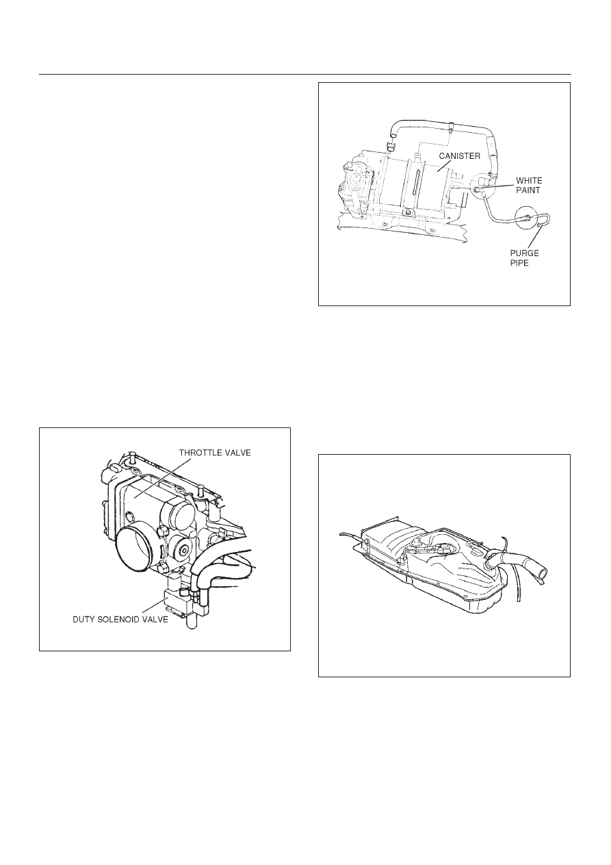
D
EVAP Canister Purge Solenoid. Normally closed, the
purge solenoid opens upon the PCM’s signal to allow
engine vacuum to purge gasoline fumes from the
canister. Mounted on the water pipe to front of the
engine assembly.
060R200080
D
EVAP Canister Vent Solenoid. Located next to the
canister, the vent solenoid opens to allow air into the
EVAP system. Fresh air is necessary to completely
remove gasoline fumes from the canister during
purge. The EVAP vent solenoid closes to seal off the
evaporative emissions system for leak testing.
060R200081
D
Fuel Level Sensor. The fuel level sensor is an
important input to the PCM for the enhanced EVAP
system diagnostic. The PCM needs fuel level
information to know the volume of fuel in the tank.
The fuel level affects the rate of change of air
pressure in the EVAP system. Several of the
enhanced EVAP system diagnostic sub-tests are
dependent upon correct fuel level information. The
diagnostic will not run when the tank is less than 15%
or more than 85% full. Be sure to diagnose any Fuel
Level Sensor DTCs first, as they can cause other
DTCs to set.
014RW114
D
Manifold Absolute Pressure (MAP) Sensor. The
PCM compares the signals from the fuel tank
pressure sensor and the MAP sensor to ensure that a
relative vacuum is maintained the EVAP system.