Isuzu Amigo / Axiom / Trooper / Rodeo / VehiCross. Manual - part 350
6E–430
6VE1 3.5L ENGINE DRIVEABILITY AND EMISSIONS
Diagnosis Trouble Code(DTC)
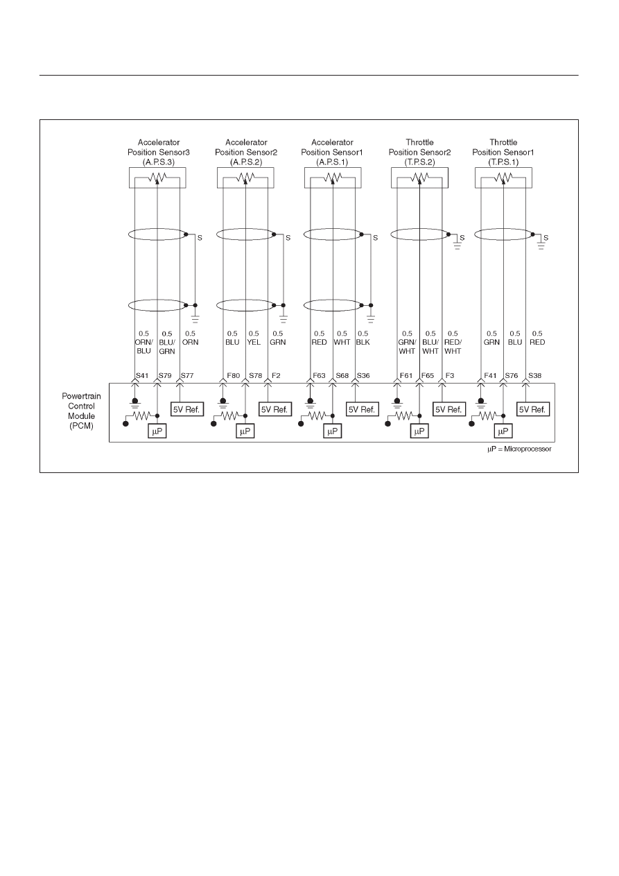
P1221 TPS1 – TPS2 Correlation(Circuit Performance)
060R200069
Circuit Description
D
The powertrain control module (PCM) controls engine
speed by adjusting the position of the throttle control
valve (DC motor). The throttle motor is a DC motor
driven by one coil. The PCM applies current to DC
motor coil in duty (%) to adjustment the valve into a
passage in the throttle body to air flow.
This method allows highly accurate control of engine
speed and quick response to changes in engine
load.
D
The accelerator position (AP) sensor circuit provides a
voltage signal relative to accelerator pedal angle.
The accelerator pedal angle (AP1) will vary from
about 13% at idle position to about 87% at open
throttle(WOT).
APS signal is used to determine which DC will adjust
throttle position.
After the APS signal has been processed by the
PCM, it will command the DC motor to move the
throttle position.
D
Accelerator pedal – Check for objects blocking the AP
sensor or pedal arm with spring, and excessive
deposits in the accelerator pedal arm and on the
accelerator pedal.
Conditions for Setting the DTC
D
The ignition is “ON”.
D
A difference of between TPS1 and TPS2 correlation of
over 6.5% within 125 milliseconds.
Action Taken When the DTC Sets
D
The PCM will not turn the malfunction indicator lamp
(MIL) “ON”.
D
The PCM will store conditions which were present
when the DTC was set as Failure Records only. This
information will not be stored as Freeze Frame data.
Condition for Clearing the MIL/DTC
D
A history DTC 1221 will clear after 40 consecutive trip
cycles during which the warm up cycles have occurred
without a fault.
D
DTC 1221 can be cleared using the Tech 2 “Clear Info”
function or by disconnecting the PCM battery feed.
Test Description
Number(s) below refer to the step number(s) on the
Diagnostic Chart:
2. Visually/physically inspect for the following throttle
valve conditions.
3.Visually/physically inspect for the following
accelerator pedal conditions.
5.Check the following circuits for throttle valve and DC
moter. Check the following TP sensor resistance
and DC motor.