Isuzu Amigo / Axiom / Trooper / Rodeo / VehiCross. Manual - part 327
6E–338
6VE1 3.5L ENGINE DRIVEABILITY AND EMISSIONS
Diagnostic Trouble Code (DTC)
P0453 Fuel Tank Pressure Sensor (Vapor Pressure Sensor) High Voltage
060R200050
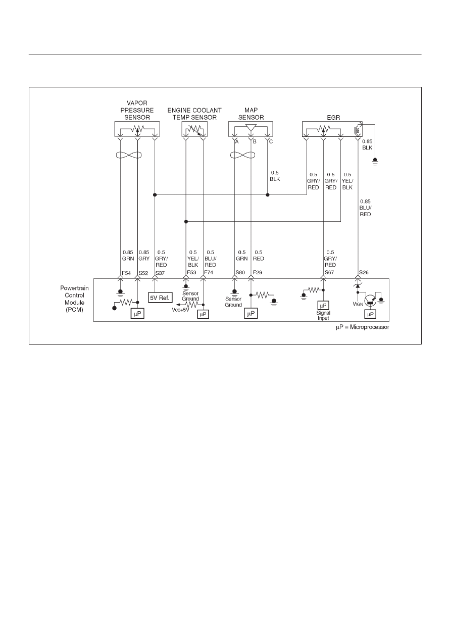
Circuit Description
The powertrain control module (PCM) monitors fuel tank
pressure sensor (Vapor pressure sensor) of the
Enhanced Evap system. When the tank pressure output
indicates high voltage , PCM will set DTC P0453.
Conditions for Setting the DTC
D
Tank sensor output is more than 4.9 volts for 12.5 sec.
D
100 test failures within a 200 tests.
Action Taken When the DTC Sets
D
The PCM will ON the MIL after second trip with
detected the fault.
D
The PCM will store conditions which were present
when the DTC was set as Freeze Frame and in Failure
Records data.
Conditions for Clearing the MIL/DTC
D
The PCM will turn the MIL “OFF” on the third
consecutive trip cycle during which the diagnostic has
been run and the fault condition is no longer present.
D
A history DTC P0453 will clear after 40 consecutive
warm-up cycles have occurred without a fault.
D
Info function or by disconnecting the PCM battery feed.
Diagnostic Aids
Check for the following conditions:
D
Open circuit of sensor ground line – Inspect wiring
harness from PCM to the sensor. The PCM turns
P0453, and P0108 at the same time.
D
Open circuit or short circuit to 5 volt reference line –
Inspect wiring harness from PCM to the sensor. The
PCM turns P0453 and P0108 at the same time.
D
Tank fuel pressure sensor malfunction may cause
P0453.
Reviewing the Failure Records vehicle mileage since the
diagnostic test last failed may help determine how often
the condition that caused the DTC to be set occurs. This
may assist in diagnosing the condition.